Pinned cylinders, punched tapes and cards. Data storage and retrieval: from music, to cloth weaving, to infotech.
Vladimir Esaulov. June 2020.
In the old days, information was stored by cutting letters and numbers into stone, writing on paper or coding it into knots on chords like on the warazan or khipu. In today’s world you take it for granted that you can perform complex calculations and use a word processor or a painting program on a computer. How was this information, in its most basic numeric form entered and retrieved from computers in the early days?
One of the first and, as it turned out, long lasting ways, was by using paper with holes in it: perforated or punched tape and cards. Punched cards were the size of paper money, with arrays of holes punched in them like on the card shown in figure 1. It might appear a little strange, but it all started at the dawn of the industrial revolution, with weaving cloth or rather with designing ways of controlling and automating the loom and a bit later also recording and playing music. Lets look at how all this developed.
We will, start with another, much older old and also very long lasting method of recording information for music reproduction and simple animation using pegged cylinders. For many years such musical organs were a very popular way of listening to mechanical music (figure 2) and even famous composers of classical music, like Mozart, Beethoven wrote short pieces of music for them.
Figure 1. An 80 column (see text) computer punched card.
A Brief Story of Early Mechanical Music.
Many of you must have seen small musical boxes and perhaps even the more elaborate ones with a ballerina or other animated figure that moves along with the music of the box. Today you frequently get an open little box, where you can see its mechanism ((figure 3) ): a small handle allowing you to rotate a little cylinder with notches or pins protruding from its surface. As the cylinder rotates, these pluck the tuned teeth of a steel comb producing musical notes. In other systems this method can be used to actuate levers in a pneumatic system that send air into an organ pipe, or raises a hammer that strikes on the strings on a chord instrument etc…
The story of this pinned cylinder device in music goes back to 9th century Baghdad at the time of the Abassid Caliphate. A Persian scholar trio, the brothers Ahmad, Muhammad, and al-Hasan, sons of Mūsā ibn Shākir (or Banū Mūsā as they are frequently called), were part of the group of scholars who introduced Greek inventions in the Arab world.
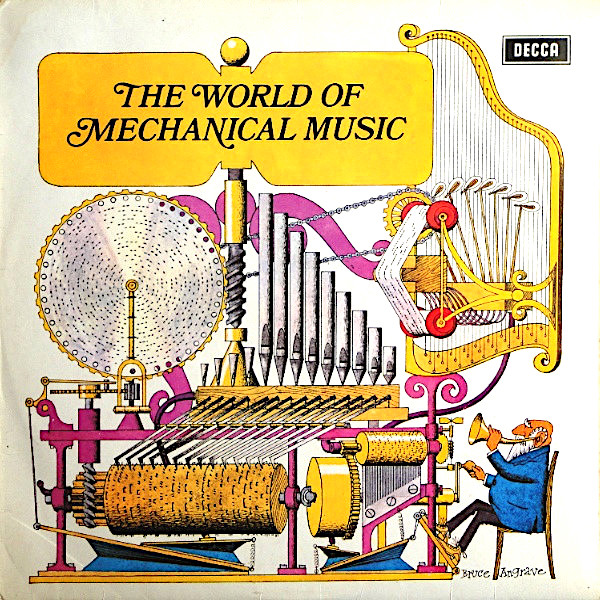
Figure 2. A vinyl record with a collection of mechanical music pieces using various instruments.
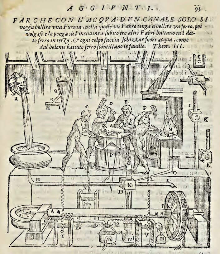
Greek inventors of the 300 BC-100 AD period, had described a variety of pneumatic and hydraulic devices, including musical organs, various gears and automatons, set into motion by complex set of pullies and cylinders with pins. These included Ktesibius, Apollonius of Perga, Hero of Alexandria and others (see e.g. Aleotti’s compilation of Hero’s inventions; Aleotti 1589). Aleotti’s drawing of one of Hero’s automatons with four blacksmiths is shown in drawing 3b. Of interest here is a cylinder with pins, which one can see in the right upper side, which served to command some of the movements of the figures.
Banū Mūsā, invented an innovative “automatic” organ, using a hydro pneumatic system to drive air into a sorna or sūrnāy flute. Our interest here is in the “programming”, pinned cylinder. They described this organ in their manuscript al-Ala allati tuzmiru bi-nafsiha: “The Instrument which Plays by Itself”. A complete translation of their text, which gives a detailed description of this ingineous device, can be found in the article of Farmer (1931).
Figure 3a. A pinned cylinder musical box mechanism.
Figure 3b. Hero of Alexandria's blacksmiths. From Aleotti (1589).
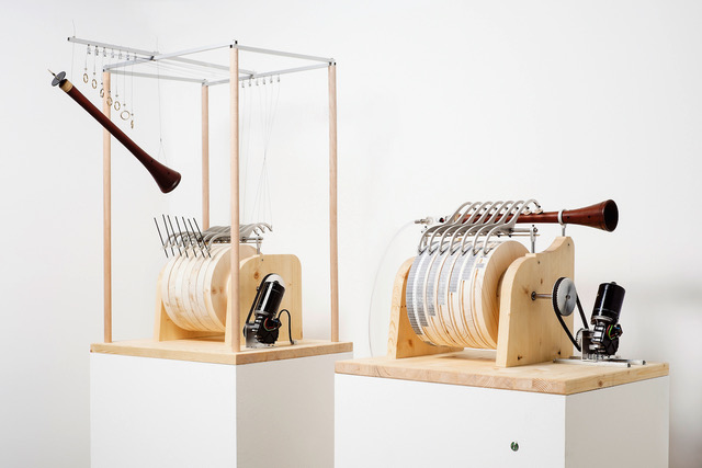
A reconstruction of their instrument following their text is shown in figure 4a. The playback part (on the right part in the figure) consisted in a system of rods. The rods were fixed on an axis that lay parallel to the flute and a pinned cylinder. One end of each rod, acting as a finger, blocked one of the eight holes of the flute. The other, opposite end touched the surface of the cylinder, the pins of which, when it rotated, moved the rods resulting in the opening and closing of the flute holes. In order to record the music, i.e. in this case to correctly place the pegs or pins on the cylinder an “inverse” system was used. Each rod was attached via a ring to a flutist’s finger by a string. The other pointed end rested on the surface of a wax coated cylinder (Figure 4a left). When the flutist played a melody, the movement of his finger, was transmitted to the cylinder via the rod. Thus, the raising of the finger from the hole of the flute would leave an engraved trace in the wax. This was done for each finger, therefore for each note played on the flute. In thismanner, the notes of the melody were engraved in the wax. Thereafter correspondingly shaped, long or short pegs (depending on the duration of the note) were fixed to the cylinder at the corresponding, appropriately positioned, points along the circumference.
Banū Mūsā suggested that the tempo of the music could be changed by varying the speed of rotation. Furthermore, to play more than one tune, the diameter of the cylinder could be enlarged or the cylinder could be lengthened and displaced axially. They discuss the incorporation of this device into a standing flute player automaton. Was this system built by them? This is not clear, but their ideas spread to Europe and inspired the building of many mechanical music devices.
Figure 4a. Reconstruction of the Banū Mūsā pinned organ system: (left) recording setup, (right) playback system. Exhibition Allah's automata. ZKM Karlsruhe. Image source: requested.
Figure 4b. Edison's wax cylinder phonograph. Here sound vibrations were recrded in the wax surface and then played back by a pickup needle. Image source: requested.
It is worth noting that their system is in some ways an interesting ancestor of the late 19th century wax cylinder phonograph (Thomas Edison, 1877) and other early 20th century audio recording methods. In some ways it has an analogy with burning holes with a laser recorder. In today’s terminology the pinned cylinder is a sort of read only memory for an analog mechanical machine.
Several centuries later the pinned cylinder system was introduced in Europe. It seems to first appear in the 13th/14thcentury. Its use spread to chimes and carillons. Large pinned-cylinder controlled organs were built, like the famous organ fountain at Villa d’Este in Rome, dating from the end of the 16th century. Penned cylinders have been used to play a variety of air and string instruments (Fowler 1967, Norrback 2010). The first detailed descriptions appeared in Europe in the texts of renown scholars, seen elsewhere in these pages, like Athanasius Kircher of the Coleggio Romano in Rome (Musurgia Universalis, 1650) and Gaspard Schott (Magiae universalis, 1657). A drawing of such an instrument along with extentions for animated figures, given in Kircher’s manuscript is shown in figure 5.
Figure 5. Barrel organ in an illustration in Musurgia Universalis ( Kircher 1650). On the sides of the large barrel one can see a mechanism for transmitting movement to dancing figurines.
While in Banū Mūsā’s description it might seem simple, the processes of transferring a larger piece of music to pins on a cylinder was in practice very complicated, requiring precise timing and creation of accurate grids on the cylinder surface. This is e.g. described in Kircher’s text, who also describes the use of paper, with a grid drawn on it, that is stuck around the barrel as a guide for pinning the music. We draw your attention to this detail for reasons that will become clear below.
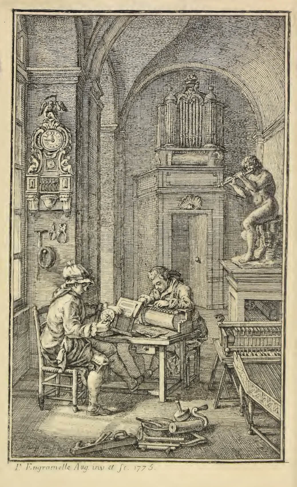
This process became the work of professionals (in French called the Noteur) and rigorous directions were laid out in 18thcentury texts such as that of the French monks Bedos de Celles (1766) and Dominique-Joseph Engramelle (1775). The latter called it the Tonotechnie method (Figure 6). Pinned cylinder systems became popular not only in large installations, but also in small portable home mechanical music boxes and persisted till the first decades of the 20th century. It is sometimes considered that the music box such as the one shown in figure 3, was invented in 1796, by the Suiss Antoine Fabre, though presumably the comb arrangement of vibrating lamellae already existed. It is noteworthy that pinned cylinders in high quality boxes had up to 10000 pins! In the 19th century radial pinned disks appeared instead of cylinders, making it easy to change disks. You can find some information on still existing music boxes on this web site.
Figure 6. A pinned cylinder workshop showing two "artists" at work in an illustration in La Tonotechnie (Engramelle 1775.) From the French description: “Le devant offre deux Artistes occupés à noter; le premier note une Serinette au Cadran: & le second note un gros Cylindre à l’Echelle…”.
The 18th century saw the introduction of a different technology involving use of perforated paper to which we now turn.
Automating the loom.18 th century programmed process control.
Cloth weaving is a very old technique developed in ancient times in Egypt, China and other regions. A loom refers to a machine that weaves threads to form a fabric. Our interest in this section is not in the weaving process, but only in an approach that was developed starting from the early 18th century to simplify and “program” the operation of a loom. First a few words about the loom along with its specific terminology appear useful.
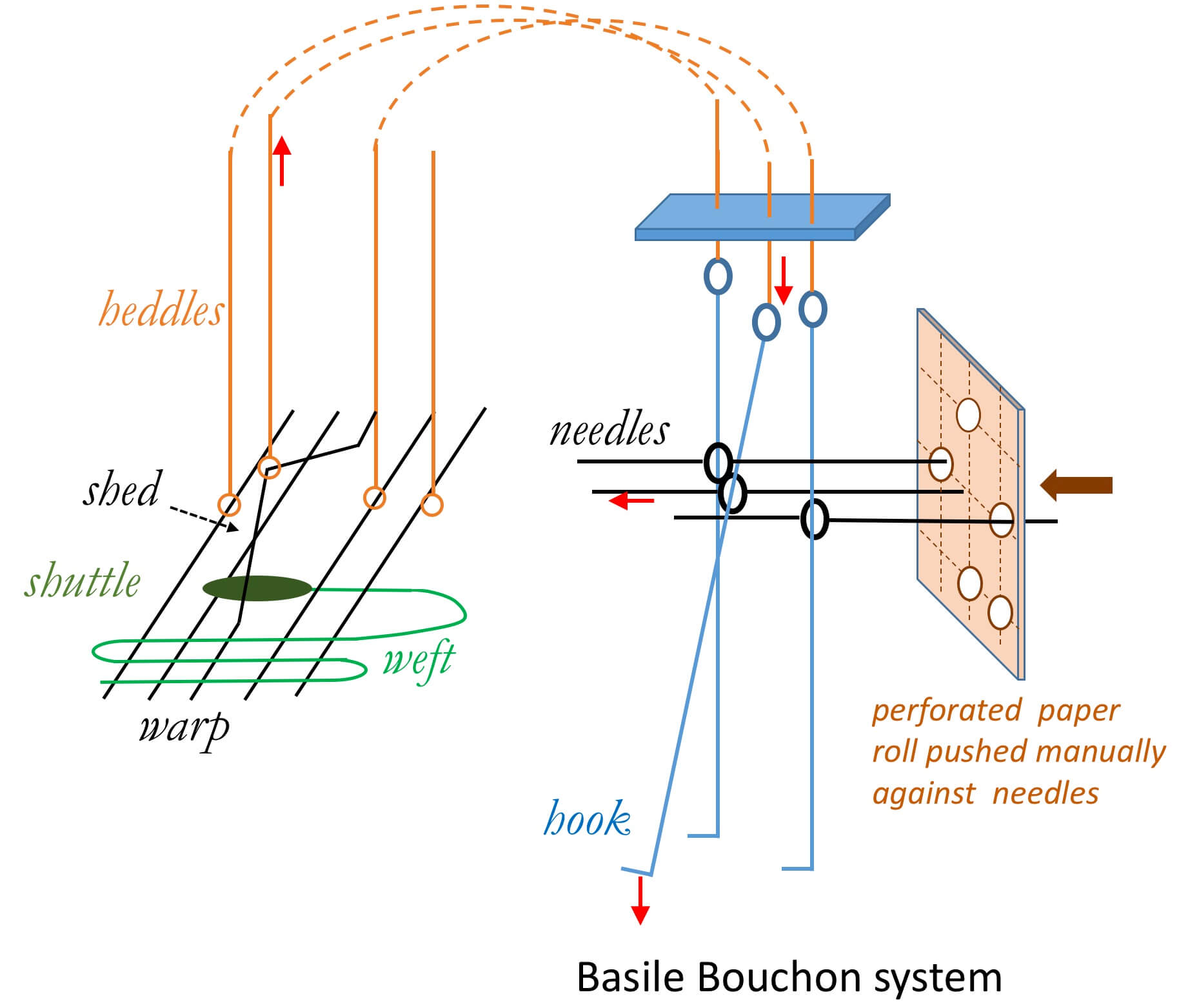
In weaving, a set of treads referred to as the warp, are held stretched tightly over a frame: the loom. Another set of threads called the weft or the filling yarn, is inserted in between the threads of the warp. Each of the warp threads passes through a heddle: a ring suspended on a wire, that allows to separate the individual threads to allow passage of the weft threads. The heddles hang from a harness. The pattern to be woven determines which yarn threads are connected to a given harness and the number of harnesses depends on the complexity of the pattern. During the operation of the loom, part of the warp threads are raised (to form what is called a shed) to allow the passage of the filling yarn that is carried by a specially shaped carrier (for ease of passage), called the shuttle. This shuttle moves back and forth across the warp. What one should retain here, is that for each row, each passage of the shuttle, a set of harnesses is raised, depending upon the pattern that is weaved. Traditionally loom operation was entirely manual and shedding, i.e. the selection of and pulling up of the heddle harnesses was done frequently by children: the so called draw boys, who worked with the weaver.
Figure 8. Simplified schematics of a loom and Basile Bouchon's system.
The inventions we shall talk about now, concern some simplifications in the loom operation and in particular the automation of the process of implementing the pattern and elimination in the need of the draw boys. This has a background in some of the previously described methods used in mechanical music. While there is no obvious reason, given the people involved it seems quite possible.
Manual looms of the type referred to here were introduced in France in the 15th century from Italy: the loom of Jean le Calabrais (the Calabrian). They had limited capabilities in terms of possible size of woven patterns. Over the next hundred years they underwent changes allowing a large increase in the number of threads and the size of patterns, … but also of the number of persons operating them. A revolutionary change was introduced in 1725 by a loom worker, Basile Bouchon (loom in figures 8 & 9), followed by a series of successive improvements and innovations by various people notably Jean-Baptiste Falcon (1728), Jacques Vaucanson (1745) and Joseph-Marie Jacquard (1804). These four main changes are illustrated in the very simplified schematic diagrams in figure 10 following the detailed descriptions by Razi (1913).
Bouchon, who was from a family of organ builders, made the first key invention: a method of selecting a pattern and raising the corresponding harnesses, using a control rod (needle or aiguille in French as he called it) and hook duo and a pattern of holes in paper. This is very much reminiscent of what was done in pinning a cylinder using a paper pattern. In his method, each row of a pattern (corresponding to each passage of the shuttle) is coded as a series of holes punched in a row across the width of a roll of paper (according to a grid marking). The length of the roll depended on the type of pattern to be woven. In Bouchon’s mechanism (figure 8) a heddle is attached to a rod with a hook that can be pulled down. This leads to the raising of the yarn thread and creation of the shed. The hook rod is attached to a needle with a ring. A series of such needles are aligned in a holder in front of the paper. The positions of the needles correspond to the grid on the paper. The weaver’s helper (draw boy) rotates the paper roll, bringing a row of the pattern in line with the needles and presses the paper manually against the needle array. If there is a hole in the grid, then the corresponding needle passes through it and is not affected by the pressing of the paper, otherwise it is pushed back. This results in a lateral displacement of the hook. All the displaced hooks (and corresponding heddle threads) are then pulled down by a bar activated by the weaver. The undisplaced hooks and corresponding yarn threads remain in place. The operation is repeated for the next row in the design. This was the first time a weaving pattern was programmed on paper, with the needles “reading” the information.
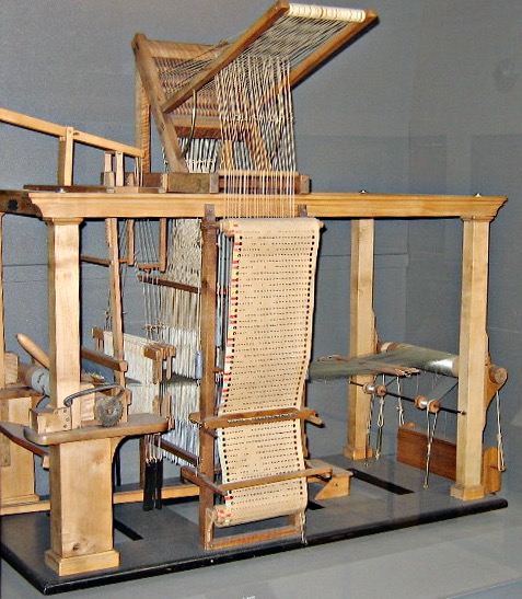
Figure 9. A model of Basile Bouchon's loom with the perforated paper control. From the Universal Exhibition in Paris 1850. Musée des Arts et Métier Paris. Image courtesy Prof. Brian Randell.
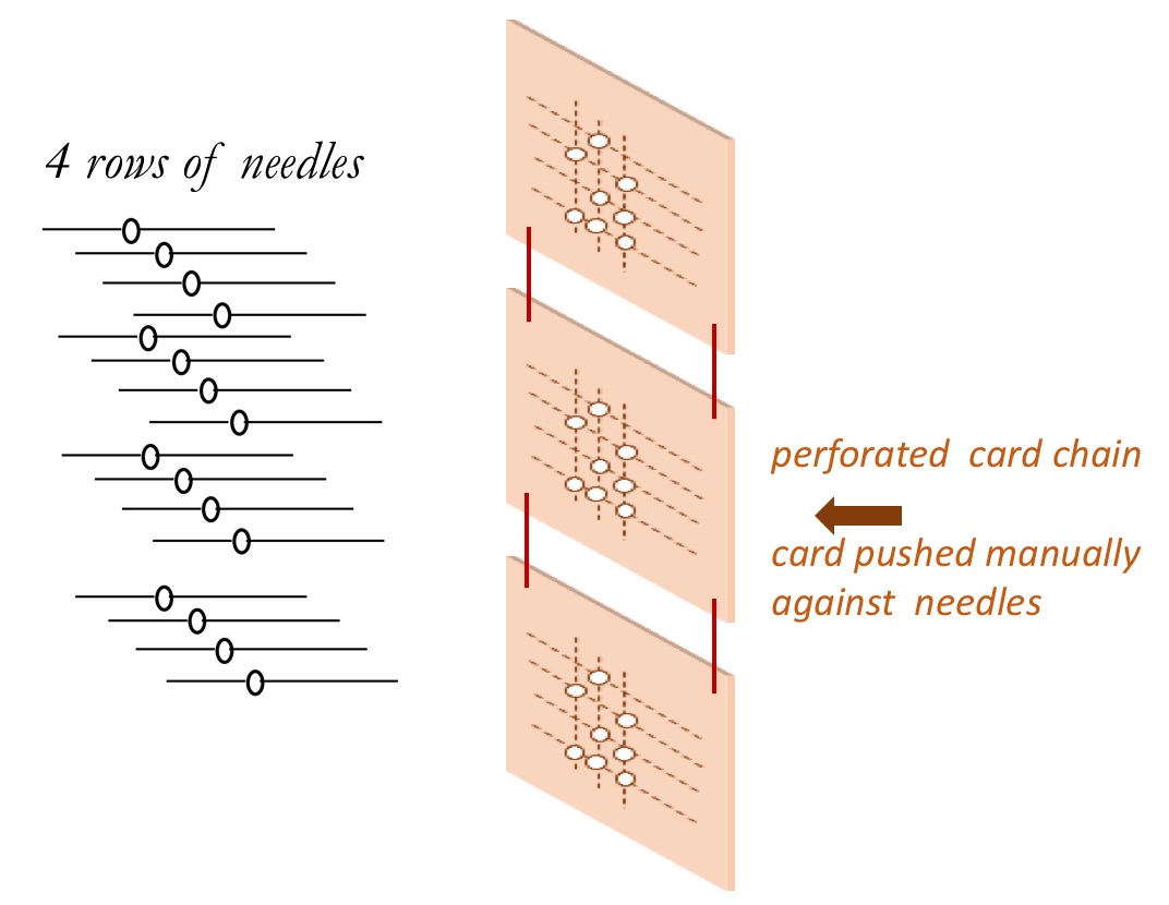
Bouchon’s method, though highly innovative, was not successful, as the number of needles was limited (typically around 800) and also the perforated paper roll was fragile. A few years later Falcon improved the system by replacing the paper roll by a series of paper cards interconnected by threads (figure 10 a,b and 11a). One card was used for one row in the pattern design. Falcon increased the number of needles by stacking them in four rows (figure 10a,b). The number of hooks increased correspondingly making the system more versatile. A big advantage was that the cards could be replaced individually. The system of operation remained manual.
Figure 10a. Falcon loom system
Figure 10b. Falcon card
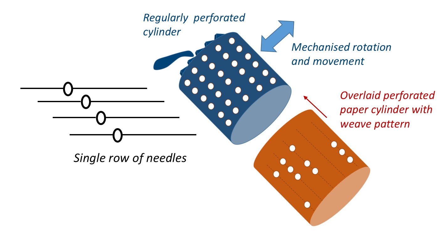
Figure 10c. Vaucanson mechanised loom system.
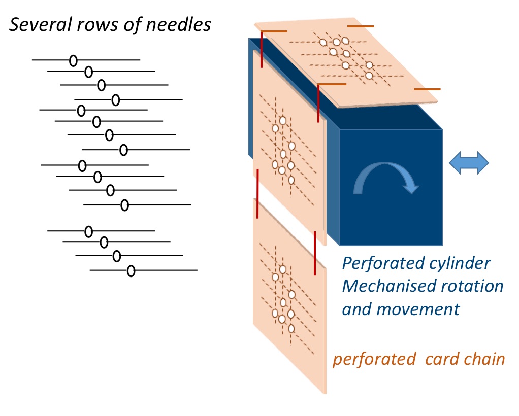
Figure 10d. Jacquard mechanised card & cylinder system
Some time later, the engineer inventor and expert in automatons, Vaucanson designed a first mechanised automatic loom. In his system he replaced the paper roll or card-chain by a rotating movable cylinder (figure 10c and 11b). The cylinder had a set of holes perforated in a grid pattern around its circumference and length. A paper with a similar grid was attached to it. Like in Bouchon’s system the paper was perforated following the weaving pattern. One grid line along the length of the cylinder corresponded to one row in the pattern. Correspondingly, there was only one row of needles. In operation the cylinder was rotated step by step. At each step it presented one pattern row and was pressed against the array of needles. If there was a hole in the paper, the needle could pass through it (and the hole in the cylinder) and its position and that of the corresponding hook was unaffected. The loom was fairly popular, but its disadvantage lay in the limited number of needles and the size of the pattern was limited by the size of the circumference of the cylinder. In both Bouchon’s and Falcon’s system the length of the programming roll of paper or card-chain was basically unlimited.
Figure 11a. A model of Falcon's loom with the perforated card control. From the Universal Exhibition in Paris 1850. Musée des Arts et Métier Paris. Image courtesy Prof. Brian Randell.
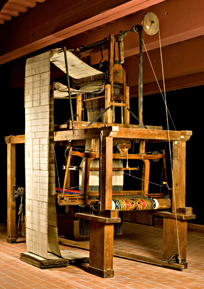
Figure 11b. A model of Vaucanson's mechanised loom with the perforated cylinder control. The paper covered cylinder may be seen on the top. From the Universal Exhibition in Paris 1850. Musée des Arts et Métier Paris. Image courtesy Prof. Brian Randell.
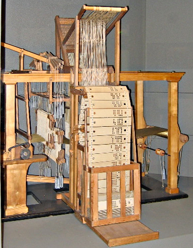
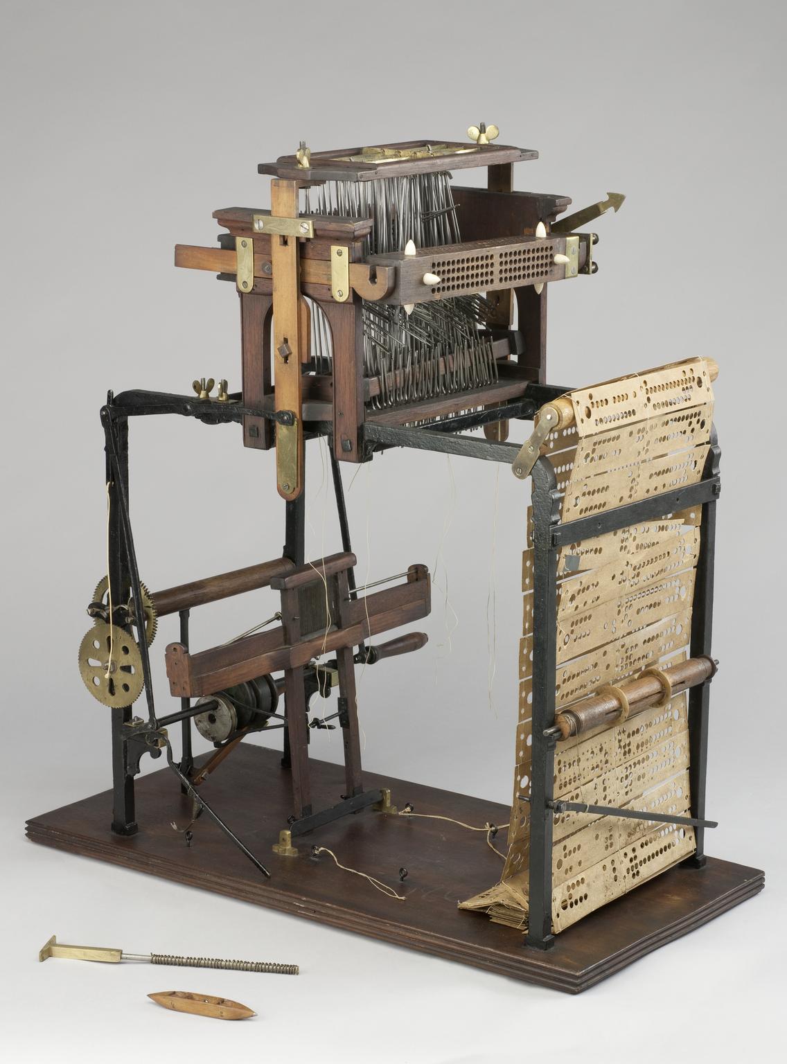
Half a century passed by, before Jacquard created a first version of his famous loom (figures 10d and 11c). What Jacquard did, was mainly to put together the inventions of Bouchon, Falcon and Vaucanson. He borrowed the rotating cylinder mechanics from Vaucanson and used the needle/hook duo of Bouchon along with the card set of Falcon. A simplified version of his pattern programming loom head is shown in figure 10d. Jacquard replaced the cylinder of Vaucanson by a parallepiped, which is still called “cylinder” (see figure 11c). This was used to position Falcon’s card in front of the array of needles, with the addition of a metal frame: the “lanterne”. For each new row in the pattern, the “cylinder” was moved back, rotated a quarter turn to bring in place a new perforated card and moved forward to press it against the needles.
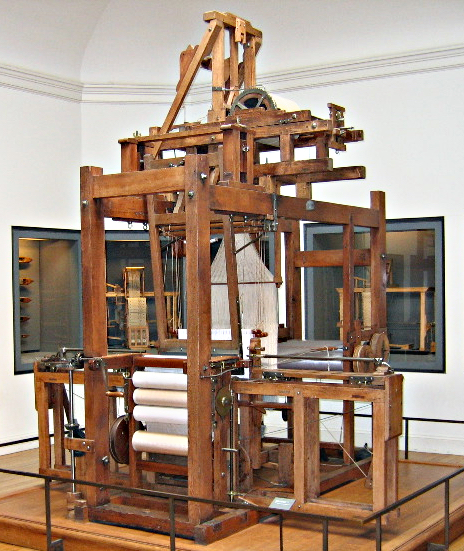
In this manner a fully punched-card programmable automatic loom was created, ushering in an era of programmed industrial process control. It is called the Jacquard loom, although really his “invention” mainly refers to the programming head of the loom. An image of the full loom presented in a Lyon Musées Gadagne may be seen here. Jacquard’s loom created unemployement, but also led to the appearance of a new specialization: the “liseur” (reader) who job it was to transcribe patterns onto cards.
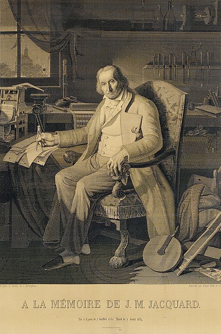
Figure 12 a. Portrait of Joseph-Marie Jacquard woven on a Jacquard loom. Source Wikipedia.
The system underwent a number of improvements by other persons before becoming really usable. Initially the cards were all prepared and perforated by hand. In 1818, M. Berly, invented a machine allowing to transfer the patterns to cards and a press to perforate the cards mechanically.
An 1839 portrait of Jacquard woven in silk on a Jacquard loom, using 24,000 punched cards is shown in the figure 12. It is a reproduction of the portrait painted by Claude Bonnefond in 1831, which is in the collection of the Musées des Beaux-Arts de Lyon.
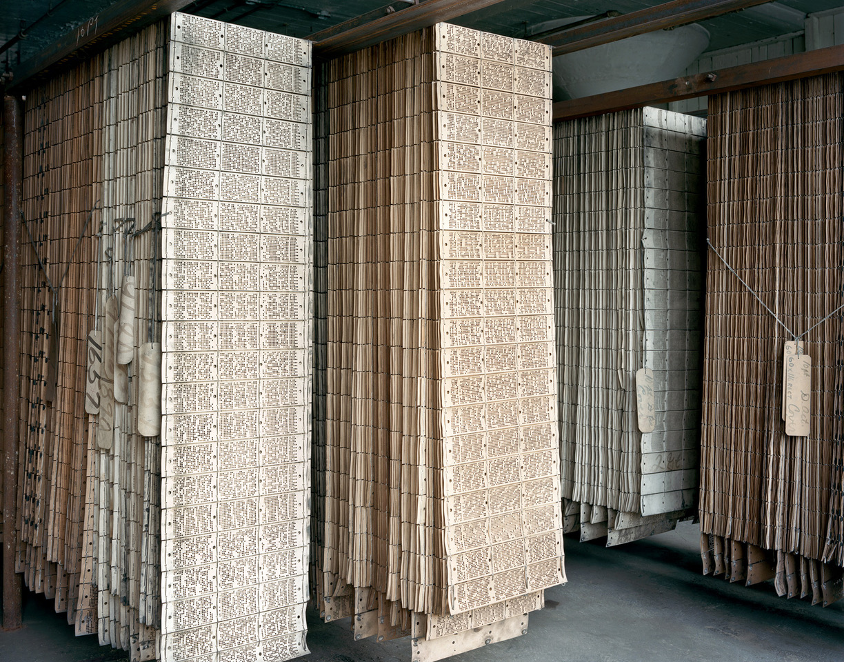
There exist many variants of the Jacquard system depending on the type of weaving to be done. Jacquard looms are used in many countries. Figure 12b shows a sets of Jacquard cards in a factory in the USA. In some parts of the world, like in India, one can still find looms, with much of the work done manually.
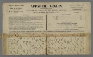
We end this section by mentioning the Appareil d’Acklin. Acklin’s objective was to replace the punched card in Jacquard’s loom by … punched paper rolls. The argument in favour of this was the ease of handling, lesser storage space and lesser cost. Acklin’s apparatus was presented at the Paris Universal exhibition in 1855. An image of a description from the Exhibition, including an example of the perforated paper is shown in figure 12c. This medium for looms and weaving machines is still being used alongside the punched cards. It is interesting that this document was found in the archives of Charles Babbage (see below and this page).
Figure 12b. Punched card chains used on Jacquard looms. The photo was taken in 2010 at the abandoned Scranton Lace factory in Scranton, PA, USA. Image courtesy of photographer Christopher Payne.
Use of Punched Tape and Cards Spreads to Other Domains.
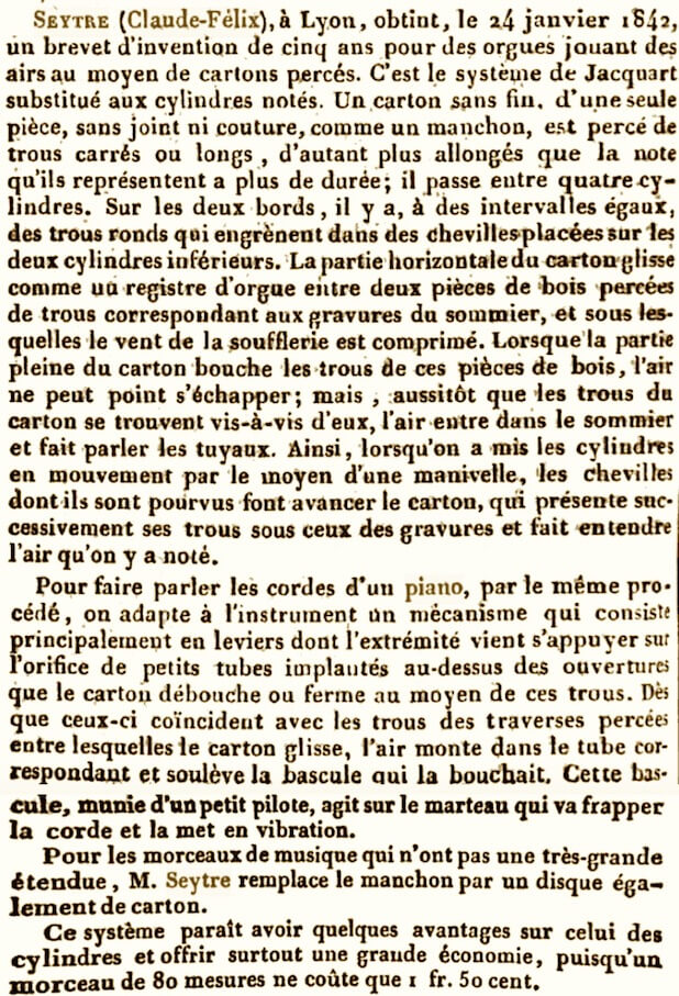
Music. It is not really surprising that quite soon, another Lyonnais, Claude Félix Seytre, invented a perforated card, pneumatic system to play an organ or piano (his Autophone; January 1842 patent 8691). As described by Marie Pierre Hamer (Hamer 1849, p 484; French text here), Seytre used Falcon-Jacquard cards, which were perforated with short or long holes and passed over air blowing vents connected to an organ. Whenever a hole was present air passed through it, for a time depending on the length of the hole, resulting in sounding of the organ tubes. For the case of the piano, passage of air through a hole pushed a lever connected to the hammer striking a piano string. For short pieces of music Seytre envisaged a cardbord disc with holes.
In 1847 the Scottish Alexander Bain Bain devised a musical box, in which air passage was controlled by a punched tape, based on his telegraph tape transmitter (see below). Concerning Seytre’s inventions, it is interesting that the German inventor Paul Lochmann proposed the use of a perforated disc in 1866.
The invention of the pneumatic mechanism led to the progressive replacement of the more complex and cumbersome pinned cylinders and as noted by Hamer reduced costs allowing wider public use.
In 1892, the Italian organ maker Anselmo Gavioli patented the “book organ“, with used folded sheets of cardboard with punched holes: a system that became very popular in organs frequently used in fairs and small street organs.
Around the 1870s, perforated paper rolls were introduced and after various iterations led to the development of the Pianola by an American engineer Edwin S. Votey in 1897. There now exist hundreds of music pieces that can be found for the Pianola and there is even a Pianola museum in Amsterdam, with a large collection of these.
Figure 13. Book music for a Gavioli organ. Image source Wikipedia.
Message transmission and typing. At the time of telegraph development, in the 1843-46 period, Alexander Bain implemented a very fast electrochemical method for recording telegraph messages, based on Edward Davy’s patent of 1838. To go with this he developed a punched tape system of transmitting messages, which was much more rapid than the previously used telegraph key.
In the 1880s the American (USA) Tolbert Lanston invented a Monotype System, in which the caster matrix for characters was transmitted as a matrix of holes on tape punched with a keyboard.
The Beginning of a New Era.
Semyon Korsakov (1787-1853), a statistician with the Russian Police Ministry in St. Petersburg and also a homeopath, proposed machines for comparing ideas, devices to select between various symptoms of diseases presented in a table on paper or wooden support as a matrix of holes. The selection was performed by a “selecting board” with needles or nails much as in the textile loom system. (Shilov & Silantiev 2017). This was described in an 1832 booklet and presented to the St. Petersburg Academy of Science.
In the 1820s the British scholar Charles Babbage (1791-1871) embarked on his many years’ work on designing computing machines, starting with the Difference Engine. The successor to this first attempt was the Analytical Engine, whose development started in the early 1830s and continued throughout Babbage’s life. The major point about this machine was that it was supposed to be completely programmable using a series of Falcon-Jacquard type punched cards, which would hold both data and the program.
The first actual use of punched cards for data storage and retrieval was made in 1880 in the USA by Herman Hollerith (1860-1929), who combined punched cards with electrical read out and filing machines to help with generating population statistics. Hollerith’s invention led to the formation of IBM and use of punched cards in computers.
We describe these developments and their application in computers that appeared in the mid 20th century in the following web page.
Korsakov, Babbage, Hollerith and Punched cards.
References and Links.
Aleotti Givanni Battista. 1589. Gli artificiosi, e curiosi moti spiritali di Herone. Zenero, Carlo. Pbl. Bologna. https://ia800209.us.archive.org/29/items/gliartificiosiec00hero/gliartificiosiec00hero.pdf
Bedos de Celles François, L’art du facteur d’orgues. (The Organ-Builder, trans. Charles Ferguson (Raleigh: The Sunbury, 1977). https://ia600305.us.archive.org/6/items/nouveaumanuelco00gugoog/nouveaumanuelco00gugoog.pdf
Engramelle Dominique-Joseph, 1775. La Tonotechnie ou l’art de noter les cylindres, facs. ed. (Paris: Hermann, 1993). & https://ia800607.us.archive.org/34/items/latonotechnieoul0000engr/latonotechnieoul0000engr.pdf
Farmer H.G., 1931. The organ of the ancients: from Eastern sources (Hebrew, Syriac and Arabic). W. Reeves. London.https://archive.org/details/TheOrganOfTheAncientsFromEasternSources
Fowler Charles B., 1967. The Museum of Music: A History of Mechanical Instruments. 1967. Music Educators Journal. v54, pp. 45–49
Hamer Marie-Pierre, 1849. Nouveau manuel complet du facteur d’orgues, ou, Traité théorique et pratique de l’art de construire les orgues : contenant L’orgue de d. Bédos et tous les progrès et perfectionnements de la facture jusqu’à ce jour : précédé d’une notice historique sur l’orgue, et suivi d’une biographie des principaux facteurs d’orgues français et étrangers. by Hamel, Marie Pierre, 1786-1879; Bédos de Celles, François, 1706-1779. Art du facteur des orgues. 1849; Guédon, Joseph. see Page 484. https://archive.org/details/nouveaumanuelco00gugoog/page/n10/mode/2up
Kircher Athanasius. 1650. Musurgia Universalis Tome II: Books 8-10. https://imslp.org/wiki/Musurgia_Universalis_(Kircher,_Athanasius)
Sanjakdar Chaarani, Mona. The Automatic Mechanical Hydraulic Organ Of BāNū MūSā Ben Shāker. https://sanjakdar-chaarani.com/new_sai_j3x/index.php/orgue-banu-mussa
Schott, Gaspard. Magiae universalis naturae et artis, pars II. Acustica (1657). https://nordnum.univ-lille.fr/ark:/72505/a011517565951WFQtho/9e9b7d7996
Shilov Valery and Silantiev Sergey. 2017; ‘Machines à Comparer les Idées’ of Semen Korsakov: First Step Towards AI. IFIP International Conference on the History of Computing (HC), May 2016, Brooklyn, NY, United States. pp.71-86, 10.1007/978-3-319-49463-0_5 . hal-01620143


