Menu Close

From Fire and Smoke Signals to the Telegraph and Telephone.

Humans since ancient times have communicated with each other by speech and writing and over distance by using messengers, using visible signals, drums and carrier pigeons. References to messengers can be found in ancient Egypt (King Sesostris I around 1950 BC) and ancient Babylon (King Hammurabi around 1770 BC). At some point, possibly partly because of the lack of safety of the messengers, guard posts were established at regular intervals in Babylonia and by 650BC, they were used for “instant messaging” with fire beacons (ref. Luckenbill). Xenophon (430-355 BC) described in his Cyropaedia and The History, that in Persia intermediate post-stations were created, which served as resting places. Messages were relayed from post to post.

The “optical telegraph” consisting in transmitting messages by visual signals such as smoke, and fire was a first step in establishing extended communication networks. The appearance of the electrical telegraph, the telephone and the radio in the 19th century changed dramatically the way people communicated. The foundations of today’s global society with computerised communications were laid  in the 1960s. On this page we look at the history of communications from the ancient times to appearance of the telegraph and telephone by wires.  Go to the WIRELESS TELEGRAPHY AND RADIO and  THE INTERNET & THE WORLD WIDE WEB pages for  later developments and the digital communication revolution. If you ask yourself the questions: who invented the telegraph? or who invented the telephone? read on…

THE ANCIENT WORLD.

GREECE 

Ancient Greeks used light beacon relays (fires) or reflected light to transmit information. Thus the play writer Aeschylus (c. 525/524 – c. 456/455 BC)) in his tragedy Agamemnon (c. 458 BC), relates how king Agamemnon’s wife Clytemenestra describes the fast arrival to her in Argos, of the news of the fall of the city of Troy (around 1100 BC)  to the Greeks, by means of fires lit up on hill tops, transmitted across land and sea and finally seen by a watchman posted on the palace roof in Argos. Excerpts from Aeschylus’  text starting with the opening words of the watchman are given in the image below (from the MIT Translation ):   

Beacons mentioned in Aeschylus' Agamemnon. Click to enlarge.
Greek warriors using beacons.

While lighting a fire only transmits just a signal, the Greeks also devised means of transmitting more detailed messages, which could also not be intercepted.

The Aenas hydraulic system. One such method was devised around 330 BC, by Arkadas general  Aenas Taktikos, and described later by  Polybius (203-121 BC) (ref. 1).  A set of messages were prepared and each was attributed a mark on a stick, which had regularly spaced markings. The stick was immersed into a tall water-filled vessel and floated vertically above the water on a cork. A tap at the bottom allowed emptying the vessel. When it was necessary to transmit one of the messages the tap was opened until the water flowed out and the stick descended up to the corresponding mark. The tap was then closed. A pair of identical setups were located on top of signalling stations. When a message had to be transmitted,  the transmitting station attracted the attention of the receiving station by lighting a torch. Once the receiving station acknowledged the signal by lighting its own torch, the transmission could begin. The transmitter then signalled to the receiver to open his tap  by hiding his torch. Both  taps were left open till the transmitter relit his torch once the stick had descended to the desired mark. This procedure  was replicated along a series of signalling stations to send messages for very long distances.  This was for  instance used for communications between Sicily and Carthage during the First Punic War (264-241 BC). 

Transmission of Words  Letter by Letter. An ingenious method for transmitting arbitrary short messages was devised by Cleoxenus and Democleitus and perfected by Polybius as described by Polybius (“Polybius, History X, 45-47”). It consisted in transmitting words letter by letter as you do in modern times. The way this was done, was to use a simple code based on tablets on which letters of the alphabet were written in groups of five (one tablet had one letter less). Transmitting stations were setup on mountain tops, with special beacons.  Each station had two sets of five torches placed separately behind two screens (or walls) set at a sufficiently large distance from each other to be easily distinguishable. The torches on the left-hand side of the “transmitter’s” beacon determined the plate number which had the desired transmitted letter and those on the right to the desired letter on that plate. The signallers at each station needed to have two “telescopic” tubes viewing each set of torches separately. The transmission of a message started as follows: the “transmitter” signalled with two torches the intent to transmit and the “receiver” confirmed by doing the same. Then both operators brought down the torches. Thereafter the “transmission” of words began letter by letter. So for instance to indicate the letter K two torches were raised on the left to select the second tablet and then five torches on the right to indicate the letter K.

Aenas hydraulic messaging system (ref 2.).
Cleoxenus and Democlitus messaging method (ref 2.).
Polybius Tablets

The Stentorophonic Tube. A huge horn or trumpet was used to transmit sounds across large distances, said to correspond to several kilometres. The horn was  hung from a tripod, so it could point in any direction. It is said, that it was used by Alexander the Great’s army during his famous expedition.

The ROMAN EMPIRE.

The Romans had also used similar burning torches as beacons to communicate over large distances. This was done, in particular, from watch towers, as illustrated (see image below) on the bas-reliefs on  the base of the Trojan Colmun in Rome, which relate the 101 AD emperor Trojan’s expedition against Dacia (corresponding to the regions of today’s Romania).  

CHINA and TIBBETT.

The Chinese had also devised a system of beacon towers along China’s northern borders. Archaeological and historical records have provided a considerable amount of information about the beacon systems of different periods, especially those of the Han and Ming dynasties (ref.3). The beacon towers (known variously in Chinese as sui, feng, fenghoutai, fenghuotai, fengsui or yandun) facilitated the relay of military and other information across the frontier by means of smoke signals by day and torch by night. The number of smoke signals or the number of times torches were raised or lowered, served to relay information regarding enemy troops. Statutes and military manuals from the Ming dynasty provide details of the rosters of troops at beacon towers, the protocol of signalling, the inclusion of cannon fire and drums within the repertoire of traditional smoke and fire signals, and some information on the fuel used for fires, which could include sulphur and saltpetre (ref.3). 

NATIVE AMERICAN SIGNALS.

The American Indians used puffs of smoke to transmit diverse types of messages. The smoke puffs were obtained by covering a fire of moist material by a blanket and withdrawing it for a short time. The number of puffs sent out corresponded to some predefined message. Alternatively, at night, they shot burning arrows across the sky. The number of flying burning arrows corresponded to the predefined message.

Stentorophonic Tube (ref 2.).
Signalling towers with torches on a basrelief of the Trojan Column, Rome.
"The Smoke Signal" (1935), dedicated to the Nebraska Indian, by Ellis Luis Burman.

17th to 19th CENTURY. 

Not much changed in communications techniques for many years following the Greek experiments. Most of the communication in Europe and a number of other regions occurred by messenger services or using pigeons. Significant changes occurred in the 17th century, which eventually led to the appearance of the first ever extensive “optical telegraph” network first in France and then in other countries in the 18th century (refs 4-8). Thus several attempts were made to build a telegraph system, amongst which the more notable ones were those done in England and Ireland by Sir Robert Hooke (1635-1703) and Sir Richard Lovell Edgeworth (1744–1817).

Robert Hooke’s Semaphore. In 1684, Hooke, known for many other seminal scientific works, devised a telegraph which he described in a lecture for the Royal Society: On Showing A Way How To Communicate One’s Mind At Great Distances. His telegraph  consisted of a wooden frame  from which large cut-out symbols could be displayed (see illustration below). The symbols did not represent the letters from the alphabet,  but rather abstract codes that could be pre-defined in a vocabulary. Hooke introduced the notion of using two classes of symbols: data or message symbols and control symbols. These control symbols were to be displayed outside the frame of his telegraph, and the data symbols within the frame. They stayed hidden behind a screen when not in use. Finally Hooke proposed an explicit protocol that would regulate the transmissions. Besides one experiment in London the device was never used.

Richard Edgeworth’s Semaphore. Edgeworth first designed his “tellograph” in 1767, which  consisted of a single large triangular pointer that could be rotated in 45 degree increments, giving eight signalling positions. If used by pairs this corresponds to 64 codes and so on. The tellograph was never used except for some public demonstrations.

The Chappe Semaphore. In 1790, to help with communications during the French revolution, Claude Chappe, with his brothers, devised an optical (semaphore) telegraph, that became  popular in Europe in the late eighteenth to early nineteenth centuries. In France its use persisted  till around 1850. Chappe experimented with various designs, the first of which in 1770, used two synchronised clocks.

The face of the clock was divided into ten parts, each part designating a different number which could be associated with a word or phrase in a dictionary. When the pointer of the clock at the transmitting station passed over the desired number, a very loud sound was made, alerting the correspondent to take into account  the number indicated by the pointer on the corespondant’s clock. In this manner a series of words in a dictionary could be transmitted. In a later version the sound was replaced by changing positions of a large movable board that could be seen from far. In 1771 a message was transmitted accross a distance of 15km. In a second version of the telegraph, because of issues of clock syncronisation, the Chappe brothers had as wrote Louis Figuier in his “Le Télégraphe Aérien” (1868) “…reduced their system to a large rectangular board, which had several sides of different colors, and which, pivoting on its axis, could present one of these six colors. The combination of the six colors, or indicators (voyant in original french text), was sufficient to represent and transmit the signals, according to a vocabulary on which was inscribed the meaning of these signals. It was not yet the current aerial telegraph, but it was the provision that later served as a model for the air telegraph in England and Sweden. However Claude Chappe was not entirely satisfied with his indicators. The discernment of colors at a distance was a great difficulty.” Note that in some descriptions this Chappe device is described as being a board or frame with movable pannels.

The first ever wide area communication network. Chappe's semaphores deployed in France. Click to enlarge.
Robert Hooke's Semaphore.
Chappe's first semaphore experiment using synchronised clocks (click to enlarge images).

The final design that was designed by Chappe and adopted in France,  is shown in the painting below. The semaphore was fixed on top of a tower. It consisted  in a pole or “mast” on which was fixed a long central “regulator” arm on a pivot. At each extremity of this arm were two shorter “indicator” arms, again fixed on pivots and each equipped with a counterweight of a distinguishably different shape. Each of these arms could be moved independently by an operator at ground using a system of ropes and pulleys. The central arm could be positioned horizontally or vertically and the side arms could be rotated by 45° into equally spaced positions (in practice 7). This allowed 98 different configurations. Some of these were identified with the letters of the alphabet as depicted in the drawing on this page.  The system could send around 2 signals per minute. An improved version was proposed later by Jacques Flocon, who set the indicator arms on a fixed bar, whereas the regulator arm was fixed alone on a pivot at the top of the mast, making the system lighter,  and easier and faster to operate (around 5 signals/minute). This semaphore was installed in many locations in France and later in Algeria. A late map is given on this page. During the Crimean war with Russia (1854-1856) a portable version was developed.

The British and Swedish Semaphores.The success of the French Semaphore induced stimulated other countries to create their own semaphore  networks. Britain adopted the semaphore of Lord George Murray consisting of a square frame with six octagonal shutters illustrated here. The shutters could be positioned vertically as shown or else rotated horizontally so that were barely visible from a distance.  This provided sixty three usable positions which could be used to encode letters of the alphabet, numerals and extra words or sentences. six shuttered panels. In 1805 Joseph Davis added a seventh sliding panel (ref.5) on the side that could be aligned with one of the three horizontal shutter rows, quadrupling the possibilities of the semaphore.  At about the same time as Murray, A.N. Edelcrantz in Sweden developed a similar ten shutter system with three vertical rows of three, four and three shutters allowing 1024 possible signals. 

Other Countries. Similar or other systems were tried in different countries  (see e.g. ref 19). Telegraph lines were built in Netherlands, Australia, USA, Prussia and other countries, including India (line between Calcutta and Chunore fortress, 1823), Egypt (between Alexandria and Cairo, 1824), Algeria (after 1844) etc. In Russia a fist telegraph was developed by Ivan Kulibin (1735-1818)  around 1794, but  the first working line was only installed following plans of  General Piotr Kozen in 1824.

“Optical telegraphy” was a big advancement in communication systems, but they were strongly limited by the necessity of having an uninterrupted line of sight between communicating points, good visibility and hence also reasonably good weather conditions5

A painting with a Chappe semaphore on a tower. (Click images to enlarge)
Chappe semaphore and Morse codes
Murray Semaphore (1795).

COMMUNICATION by TELEGRAPH and  TELEPHONE 

In the 18thand especially 19thcenturies, a number of classical experiments on physics on the physics of electricity and magnetism, led to the discovery of electromagnetic induction and electromagnetic waves and ultimately to the formulation of the theory of electromagnetism of James Clerck Maxwell in his works published between 1856 and 1873. It was found that an electric current in wire induced a magnetic field around it and that movement of magnets provoked electric currents in conductors. This resulted in the creation of the electromagnet, the microphone, the electric motor etc… It was demonstrated that it was possible to activate electromagnets remotely by wire. All this rendered possible the invention of the electric telegraph followed by the telephone. Later experiments on emission of electromagnetic waves led to the radio. Today one may also not realise that in those days appropriate materials, such as insulation of wires, were not readily available. The  slow development and improvement of all these systems was accompanied by evolution of the materials that were used.

The Electric Telegraph.

A number of telegraphs, using initially static electricity and then electric currents, were invented in the first half of the 19th century (see a very nice history by Fahie 1884). We stop here only on some well known working systems that were put to practical use.

The first needle telegraph. In Russia, Pavel Lvovich Schilling von Cannstadt (1786-1837) developed a telegraph based on Oersted’s observation of the deflection of a compass needle by a an electric current flowing in a nearby conductor (Fahie 1884, Yarotsky 1982). In the 1809-1811 period, Schilling worked with the Russian Ministry of Foreign Affairs and was posted at the Russian embassy in Germany in Munich, where he worked on telegraphy as a hobby. He participated in experiments on an electrochemical telegraph of  the physicist Samuel Thomas von Sommering. Upon returning to Russia in 1812, he first made a version of the electrochemical telegraph, but its development was not supported by the then tsar Alexander I. Following H.C. Oersted’s experiments on deflection of Compass needles by electric currents in 1820, Schilling devised needle telegraphs based on this observation. The telegraphs used one to six needles to represent the Russian alphabet and numbers.

Schilling’s six needle telegraph consisted in an emitting and receiving station connected by eight wire, six of which were used for transmitting  codes for letters of the alphabet and numbers. One wire was used for the return signal and one had been added for ringing a bell indicating transmission. The six wires were each connected to a galvanometer. When the operator depressed a key the associated galvanometer needle was deflected. The positions of the six galvanometer needles indicated the code for each letter or number. He demonstrated the telegraph in 1832. The first demonstration was in an apartment and was then rendered more realistic by using a circa 2 km length of wire. The demonstration was performed in the presence of the tsar Nicholas I, who approved its development.  The telegraph was demonstrated in various European cities in 1835 and Schilling even got a proposal from the British Government, who was interested in buying his invention. A project for an installation of the telegraph between the city of Kronstadt and Peterhof (near St.Petersburg) was entrusted to Schilling, but was not implemented due to his death in 1837. Schilling also devised a single wire telegraph and had tried to develop a recording telegraph. Following Schilling’s death one of his assistants, the physicist Boris Semyonovich Yakobi (1801-1874), developed a recording telegraph that was demonstrated in 1841 and deployed on a 25km line between St.Petersburgh and Tsarskoe Selo (Pushkin town) in 1843 (Yarotsky 1982).

Schilling’s demonstration in Germany was attended by the physicist Georg Wilhelm Muncke who copied Schilling’s apparatus to use it for demonstrations in his lectures. The telegraph was seen at one of these lectures by Sir William Fothergill Cooke (1806-79) in 1836, who decided to build one in the UK.  Cooke wrote about this (not knowing about Schilling; Cooke (1866)): “About the 6th of March 1836, a circumstance occurred which gave an entirely new bent to my thoughts. Having witnessed an electro-telegraphic experiment, exhibited about that day by Professor Moncke of Heidelberg, who had I believe taken his ideas from Gauss, I was so much struck with the wonderful power of electricity, and so strongly impressed with its applicability to the practical transmission of telegraphic intelligence, that from that very day I entirely abandoned my former pursuits, and devoted myself thenceforth with equal ardour, as all who know me can testify, to the practical realization of the Electric Telegraph; an object which has occupied my undivided energies ever since“.

The Cooke and Wheatstone needle telegraphs. Cooke involved  Sir Charles Wheatstone(1802-75) in the development of an improved version of Schilling’s telegraph (Fava Verde 2017, Cooke 1856, Fahie 1884). The telegraph needles were made to point to a specific character out of a set marked on a board.  The number of needles determined the number of characters that could be selected in this manner. This invention was adopted by the British Railways. The first commercial system was installed on the Great Western Railway in 1838. The original five needle “triangulation” system of this telegraph is shown in the image below. One of the drawbacks of the system was that it required a number of wires to transmit the information and the readout was not fast.

Wheatstone and Cooke also devised an ‘ABC’ type telegraph transmitters/receivers around 1840, with the aim of devising  systems that did not require knowledge of a code (rightmost panel in the figure below). The ABC telegraph worked like a rotary telephone dial and could be used with little training. Several variants of the system were designed. In the transmitter in the centre to transmit, letters were selected by pressing the appropriate buttons and rotating the handle continuously. The indicator stepped round the dial until the desired letter was reached, sending the correct number of electrical impulses to the receiver whose indicator stepped round in unison. It was slow, only transmitting 15 words a minute, but was simple to use.shown in the image below (center).   The system on the left was designed to be both a transmitter and a receiver. Rotation of the outer dial was used to pick and transmit characters using make-and-break contacts beneath the dial.  The pointer was used when signals were received, and rotated depending on the number of signals received. 

wheatstone 5
The Wheatstone Cooke 5 Needle Telegraph (click images to enlarge). Source: Science Museum, London
Wheatstone one
The Wheatstone Cooke 1 Needle Telegraph (click images to enlarge). Source: Science Museum, London
Wheatstone Cooke ABC Telegraphs (Click to Enlarge).Source: Science Museum, London

The Morse-Vail telegraph. On the other side of the Atlantic, also in 1837, Samuel Morse patented his version of a recording telegraph developed with Alfred Vail (1807-59). Vail, made a number of important contributions to the telegraph,  for which he does not get due credit. His notes  may be found at the Smithsonian institution (ref). Their system was very simple basically consisting of a contact key and an electromagnet. The operator depressed a key which closed a circuit and passed a current through a circuit, that activated an electromagnet at a remote receiving station. A stylus embossed dots and dashes on a moving paper tape. Vail and Morse  developed a system that represented letters in the alphabet as a series of these dots and dashes, which came to be known as the Morse code (see image above). Operators used it to encode and then decode transmitted messages. The first public demonstration of the system occurred in 1838. The first telegraph line was however only inaugurated in 1844 between Washington and Baltimore by sending the message “What Hath God Wrought” that you may see printed on commemoration stamps.

Simplified diagram of the Morse Vail Telegraph. Below left the Morse- Vail telegraph key, believed to have been used in the first Baltimore –Washington Transmission. © American History Museum. 1844 Smithsonian reference: EM181411. Below right: This telegraph receiver associated with United States patent 4,453 granted in 1846 to Samuel Morse. Museum of American History. EM.251265. . © American History Museum.
Replica of Morse's first model of telegraphy apparatus, 1835. Source: Science Museum, London
100th Anniversary of the first Morse message: "What Hath God Wrought" sent from Washington to Baltimore.
Larriviere Monaco-Morse-Telegraph-150th

Later, instead of the printed Morse code system, on the receiving side the electromagnet moved a small lever that produced audible clicks. The operator could distinguish dots and a dashes by the short or long interval between the two clicks. Eventually the whole system was automatized and replaced by keyboard input at the transmitting side and conversion of received code into typographic characters. 

The Baudot printing telegraph. In 1874, the French engineer Émile Baudot patented a printing telegraph in which the signals were translated into typographic characters, assigned a five bit code. The Baudot telegraph system allowed several telegraph messages, to be sent along the same wire “simultaneously”. It was done by several operators working in exact synchronisation with each other, sending their segment when a ‘cadence note’ sounded. The Baudot code later formed the basis of the five-unit teleprinter code.

Hughes telegraph. Another printing telegraph shown here  was invented by David E Hughes (1829-1900) around 1855. The transmitting and receiving machines were identical and worked in time with each other, working via clockwork. The pressing of any key caused an electrical current to pass through the line and activate the receiver at the other end, which then recorded the character on a strip of paper. The keyboard was similar in appearance to that of a piano, with keys for the alphabet and some punctuation characters. Hughes’ telegraphs were mostly used on submarine cables to Europe. 

The number of telegraph lines increased with time. Transatlantic cables were laid around 1858 and the London – Bombay telegraph line was completed by 1870. The first underwater lines unfortunately failed within a few weeks because of insulation problems. Some time would pass till reliable links were established. Before the transatlantic  telegraph, a message from Europe to America would travel by ship and took a week, whereas the telegraph transmission was practically instantaneous. The telegraph enabled fast financial transactions. 

The 19th century telegram service continued till the 21st century. The last telegram was sent in India on 15 July 2013 and in France on 30 April 2018. 

Baudot 5 bit code
Baudot five key keyboard (without message desk) with 'send' and 'receive' switch for simplex working,  1897-1926. Source: Courtesy of Science Museum, London.
Hughes Printing Telegraph
Hughes Printing Telegraph. 1860. Source: Courtesy of Science Museum, London.

 The Telephone.

The desire to transmit voice over large distances is a very old one as one can judge from the Greek stentorophone.  In the 18th century, an attempt to do this involved usage of long pipes (ref.4, ref.6) in the experiment of the cleric Dom Gauthey in Paris in 1782 (see image below; ref 4), who transmitted sound over a distance of 800 meters. Around 1667 Robert Hooke had experimented on transmission of sound along a stretched taut wire. An example of a device of this type is an acoustic tin can telephone in which the bottom of two cans are connected by a wire. Mechanical vibrations excited by sound waves in the diaphragm or bottom of one can, are transmitted by the wire and result in audible vibrations in the diaphragm or bottom of the second distant can.  In the electric telephone a modulated electric current is produced in the microphone by some coupling and on the receiving side the modulated current transmits the vibrations to the diaphragm of the earpiece loudspeaker by means of an electromagnet. 

Dom Gauthey's voice transmission through a pipe. 1782.
Tin Can Telephone and the Electromagnetic Telepghone of A.G.Bell

Initially there was interest in creating a “harmonic telegraph”, a device that would transmit several signals along a telegraph line. Experiments involved placing tuned vibrating reeds near electromagnets, that induced currents of different frequencies in the single telegraph wire. This eventually led to research on transmitting and receiving voice signals.

Elisha Gray Telephone Diagram in his Caveat (from Wikipedia) and a comparison with the microphone used in A.Bell's test.
Part of Chicago Tribune page showing Meucci's teletrofono.
Stamp Showing two persons talking with the help of Meucci's teletrofano. Drawing by Nestore Corradi done for Meucci in 1858.

Great effort was devoted to create devices that would transform mechanical vibrations into a modulated current without causing substantial distortions. Some 30 years after the telegraph, electric telephone communications were finally rendered possible.  A number of persons were involved in this invention and its paternity intensely disputed (refs 13-17).

The first concepts of an electromagnetic speach transmission device appear due to Innocenzo Manzetti (1944 according to Wikipedia) in Italy and Charles Bourseul (1954) from France. Bourseul gave a brief theoretical description of an electromagnetic current interrupting device withmembranes that could be used to transmit speach (Transmission électrique de la parole in “L’Illustration”, 26 August 1854). This was never constructed. Manzetti built a “speaking telegraph” that could actually transmit more or less understandable speech around 1864-65, a mention of which appeared in 1865   in the newspapers La Feuille d’Aoste  and “Le Petit Journal” in Paris in 1865 (images below). 

Other inventors at the time include Johann Philipp Reis, who made a demonstration in Germany in 1861, Antonio Meucci, who filed  a caveat (i.e. intent to submit a patent application, with brief description) to the US patent office in 1871.  Elisha Gray and Alexander Graham Bell  both submitted respectively a caveat and patent application in February 1876.  In July 1876 Bell, along with his collaborator Thomas A. Watson, performed a successful demonstration of his induction telephone at the Centennial Exhibition in Philadelphia. That year, Bell launched a telephone company using this design.

Le Petit Journal article on Manzetti. The telephone is mentioned in the last column. Click to Enlarge. ( Source gallica.bnf.fr / BnF , Paris)
Johann Philipp Reis Telephone Memorial Stamps.

There were a number of lawsuits against Bell on the ground that his work was at least partly based or inspired by that of others. It is interesting to stop shortly on some cases, which  result in ongoing debates about the paternity of this invention. 

Before going further it is interesting to point out, that the inventors were not obliged to show working prototypes of their instruments!

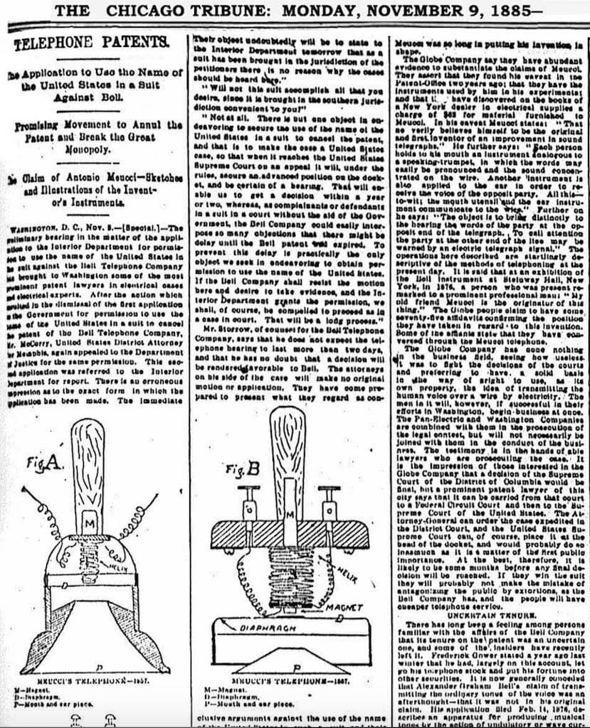
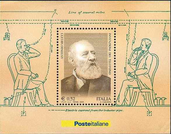
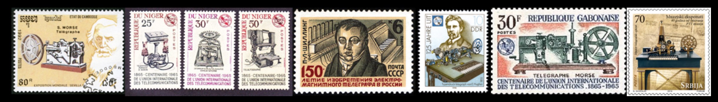
Meucci’s invention concerned an electromagnetic induction telephone on which he had worked for several years and which was supposedly described around 1860-61 (refs 13,14) in a New York Italian language newspaper Eco d’Italia (no available copy). Meucci filed a caveat, covering what he called his “teletrofano”  entitled “Sound Telegraph,” (No. 3335) in 1871, which lapsed in 1874. This caveat is not particularly clear about the use of electromagnetic induction.  In 1858, Meucci had asked an Italian painter Nestore Corradi to make drawings of his telephone represented on the first day issue Italian stamp here. Interestingly Meucci’s notes (ref 13) show that he considered  the use of induction coils along the telephone lines, which are used to minimise capacitance effects, a feature which appeared years later in telephones. An image of the teletrofano appeared in the November 9, 1885 article of the Chicago Tribune concerning his case against A.G. Bell. In  1877 the US Government  moved to annul  the patent issued to Bell on the grounds that Bell had access to Meucci’s materials.  However the case was closed as Meucci died in 1889. In 2002 the US Congress resolved “That it is the sense of the House of Representatives that the life  and achievements of Antonio Meucci should be recognized, and his work in the  invention of the telephone should be acknowledged” (resolution  H.Res269).

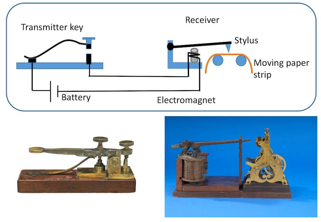
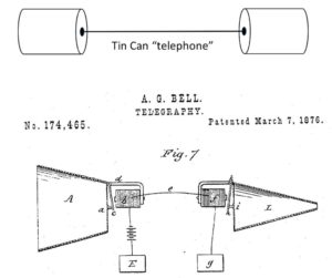
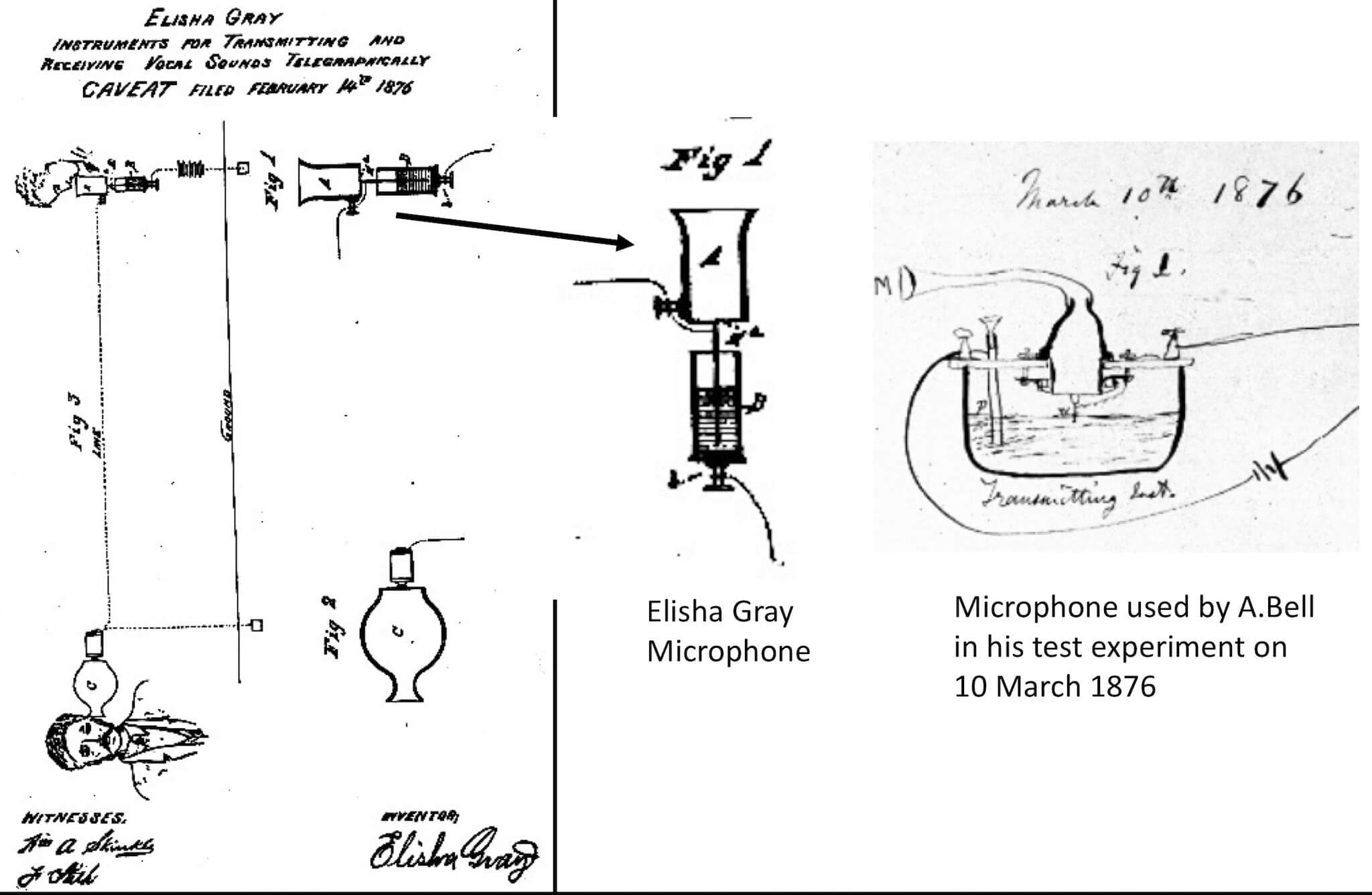
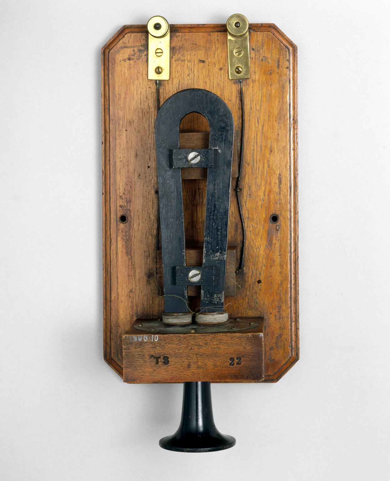
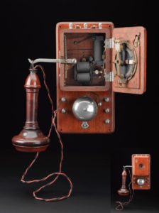
Much ink has flowed concerning the Gray-Bell dispute (refs 15-18).  Grey’s caveat described a water microphone consisting of  a diaphragm with a needle placed over a cup containing some acidulated, somewhat conducting water. The needle was immersed into the liquid and placed close to a fixed electrode (see image of Grey’s caveat). A voltage was applied to the needle and the fixed electrode. Sound waves would cause the needle to move in the water, changing slightly the needle-electrode distance and consequently the resistance across the liquid gap. This modulated current was transmitted to the receiver. Much litigation arose because this type of microphone was not in Bell’s original patent application (initially submitted in the UK), but  a reference to variable resistance acidulated water transmitter appears to have been added at the last minute of the patent submission in the US. In the preceding years Bell had experimented with liquid microphones (see refs.17). A liquid transmitter, though of a somewhat different design, involving a metal contact just touching the surface of the water,  was  successfully tested by Bell, a few days after his patent was granted in 1876 (see images above). This initial successful test  was not reproducible consistently and Bell’s successful demonstration at the Centennial Exhibition in Philadelphia was done with  his induction telephone.  In 1877 Bell’s was granted a U.S. patent for this original work on an electromagnetic induction telephone, which was designed using permanent magnets and an iron diaphragm.

The controversy regarding Bell versus Grey and others is still alive (see refs. 13-17 ).

Early type of Bell transmitter with membrane diaphragm, made by Charles Williams Jr,, Boston, United States, 1875-1914. This is an exact replica of Bell's first telephone made in June 1875 and was made by the same maker, Charles Williams Jr. of Boston. Source: Science Museum London.
Early Bell telephone instrument used at Lloyds Station (UK) 1877. It was the first telephone to use a permanent magnet, which avoided the need for a battery. The small horn could be used as both a mouthpiece and an earpiece. The mouth/ear piece is not original and was added by the Science Museum (London) in 1906. Source: Science Museum, London.
One of the first Bell telephones to be made in the UK by the India Rubber, Gutta-Percha and Telegraph Works Company Limited, Silvertown, 1878. It uses a permanent magnet, housed in the handle and was both a transmitter and a receiver. For convenience two such instruments were often used at each station. Source: Science museum, London.

The Bell patent having been granted, his telephone system was developed progressively in the US, but with some immediate changes. A much more efficient microphone, using a variable resistance carbon transmitter, was developed independently around 1877 by David Edward Hughes in England and Emile Berliner and Thomas Edison in the US. In this microphone a carbon powder button was compressed by a diaphragm subjected to sound vibrations, thereby changing the resistance of the carbon button. This resulted in the modulation the current is response to the sound vibrations. Berliner’s patented microphone was initially used by Bell telephone, but after a long litigation the patent was granted to Edison in 1892. The early telephone connections involved direct connection between two telephones. In 1876, the Hungarian engineer Tivadar Puskás invented the telephone switch, which allowed creation of telephone exchanges. The phone to phone connection system was replaced by manually operated switchboards. Telephones were thus connected to a local switchboard office, a network which became completely automated in the early 1900s.

COULD YOU DO WITH THE TELEGRAPH WHAT YOU DO WITH THE INTERNET?  Remote Chat and Games ? 

It may seem that the worlds of the telegraph and internet are completely different. There are similarities however: both serve to send images almost instantaneously, in both cases the messages are encoded (and can be encrypted) and finally in both cases the user of course has to pay the service. Also in both cases you can remotely chat and play with somebody.  There is even an 1880 book: “Wired Love”  that describes a chat love affair between a young woman telegraph operator and  a man she meets “on the wire.”  She even uses telegraphic abbreviations like G.A.: Go Ahead, as you would on your smart phone. When the first telegraph communications were established both in the USA and the UK the inventors promoted their  communication systems by organising draughts (checkers) and chess games. Thus the first games were organised between players in Baltimore and Washington in 1944 and in 1945 between Portsmouth and London involving the then British chess champion H.Staunton. See the notes from the Vail notebooks below and ref. .

The Eastern Telegraph Company network in 1901. Source: Wikipedia.
Vail's notes on Telegraph Chess Games. (refs. 9-11)
Romance on the Telegraph. (ref 12).

FIRE SIGNALING in the 21st CENTURY.

So has communication by burning a pile of wood or torch disappeared? Not quite. Recently, in 2009,  George Whitesides (USA) and others described a method of transmitting  coded information by burning strips of flammable polymer nitrocellulose patterned with alkali, alkali earth or transition metal salts, they call an “infofuse”. The alkali atom pattern encodes the information.  When the fuse is lit it burns slowly transmitting a sequence of light pulses (at 5–20 Hz) that correspond to the sequence of metallic salts and hence to the encoded information (see image below). The wavelengths of 2 consecutive pulses of light, corresponding to atomic or molecular emission, represent each alphanumeric character so a multicolored binary code is transmitted.  When burning, nitrocellulose does not produce much smoke that would obstruct the view of the  emitted light pulses, which can be detected using a CCD camera and then decoded. In their proof of principle the authors transmitted the phrase “LOOK MUM NO ELECTRICITY”.

Miscellaneous Images.

Infofuses designed by Whitesides Group. and others (ref 18).
Aenas Telegraph (Musée de la Poste)
Cleoxenus and Democleitus telegraph (Musée de la Poste, Paris)
History of Telegraphy by I.Chappe. The Original Source....

REFERENCES.

  1.  Polybius Histories X p-43-47. Link.
  2. The “bas reliefs” shown here are plaster casts made by OTE Group Telecommunications Museum on the basis of 17th and 18th century engravings. Private communication  by Constantinos Tanis. Director of Operations & Exhibitions Thessaloniki Noesis Science Center. Greece.
  3. Wolf Smoke Signals War“; chinaheritagequarterly.org
  4. Louis Figuier, Les Merveilles de la science ou description populaire des inventions modernes. Furne, Jouvet et Cie, 1868 (2, p. 1-84).
  5. The Penny Cyclopaedia Of TheSociety For The Diffusion Of Useful Knowledge, Volume 24, p.148

  6. Gerard J. Holzmann, Bjorn Pehrson, The Early History of Data Networks , 1994, Wiley. ISBN-10: 0818667826.

  7. I.Chappe. Histoire de la Télégraphie. 1824.

  8. R.Gachet. Le Télégraphe Optique de Claude Chappe. 1993. ISBN. 2950769802.

  9. Early History of the Electromagnetic Telegraph. From Letters and Journals of Alfred Vail. Arranged by his Son, J.Cummings Vail. 1914, Published by Hine Brothers, New York.

  10. A.Vail, The American Electro Magnetic Telegraph: With the Reports of Congress. Philadelphia, Lea & Blanchard, 1847

  11. Simone Müller-Pohl. “Chess by Cable: On the Interrelation of Technology and Sports in the Making of the Modern World.” Icon, vol. 19, 2013, pp. 113–131. JSTOR

  12. Thomas C.Jepsen. My Sisters Telegraphic. Women in the telegraph Office. 1846-1950.  Ohio University Press. Athens. 2000. ISBN 0821413430 / 0821413449

  13. An Article on Meucci’s telephone with diagrams referring to 1870.: http://www.interestingamerica.com/2010-12-02_Garibaldi_Meucci_Museum_Grigonis.html

  14. B. Catania, The U.S. Government Versus Alexander Graham Bell: An Important Acknowledgment for Antonio Meucci, Bulletin of Science, Technology and Society , 22, pp. 426 – 442, 2002. https://doi.org/10.1177/0270467602238886

  15. B.S.Finn, Bell and Gray: Just a Coincidence, Technology and Culture, 50, 193-201, 2009. DOI:  10.1353/tech.0.0213
  16. Ch. Beauchamp. Who Invented the Telephone?: Lawyers, Patents, and the Judgments of History, Technology and Culture, 51, pp. 854-878, 2010

  17. Elisha Gray and Alexander Bell Controversy Wikipedia Article.
     
  18. S.W. Thomas III, et.al.  2009, Infochemistry and infofuses for the chemical storage and transmission of coded information. Proc. Natl Acad. Sci. USA 106, 9147–9150

  19. Shilov V. , V. Kitov V.  and Nazarov Y. 2012.  “Optical telegraphy in Russia: 1794–1854,” 2012 Third IEEE HISTory of ELectro-technology CONference (HISTELCON), Pavia, 2012, pp. 1-9, doi: 10.1109/HISTELCON.2012.6487576.

  20. Fahie, John Joseph. 1884. A history of electric telegraphy, to the year 1837. London, New York, E. & F.N. Spon. https://archive.org/details/cu31924031221249

  21. Cooke, William Fothergill. 1856. The electric telegraph : was it invented by Professor Wheatstone ?.  London, page 14 (1856) https://ia800504.us.archive.org/7/items/electrictelegrap02cook/electrictelegrap02cook.pdf

  22. Fava-Verde Jean François. 2017. A tale of two telegraphs: Cooke and Wheatstone’s differing visions of electric telegraphy. Science Museum Group Journal. DOI: http://dx.doi.org/10.15180/170804