Menu Close

The Proportional Compass or Sector and its History.

The Proportional Compass or Sector was an analogue computational devices allowing to perform easily diverse arithmetic and geometric operations. They appeared in renaissance Europe starting around the 15th century, though their origins go into ancient times. These are generally composed of two arms with scales on them connected by a hinge.  A sector was made of brass, bone, or wood. Most are of the order of six inches long when folded.

The sector’s functioning is based on proportionality between the corresponding sides of similar triangles, based on Thales’s theorem. It was used in association with a pair of dividers, which served to measure distances and transfer the values to the scales. This determined the appropriate opening of the  legs and the answer, corresponding to the correct proportion, was then read off using the dividers directly  from the appropriate scales. The sector thus allowed quick solutions of many problems characterized by proportionality and could be used by persons with little education.  Their development was in part stimulated by development of artillery and military constructions.

1630 sector with dividers. Mathematisch-Physikalischer Salon (Zwinger), Dresden, Germany (source Wiki).

The sector  was intitially used to scale up or down figures, but later this extended to many other uses, including determination of irrational fractions,  fractions of a degree for navigation purposes, cartography, determining the size of polygons inscribed in a circle e.g. for construction of fortifications, determination of the “calibre” of gun projectiles: determination of the relation of size to weight depending on the material used, etc…

Sectors became very popular calculating instruments,  especially following the appearance of Galileo Galilei’s sophisticated multipurpose version (1597), and remained in use until the nineteenth century, when they were replaced by slide rules and mathematical (logarithmic) tables. A brief timeline of their development is given here. A detailed discussion may be found in the  other sources cited at the end (see in particular F.Camerota  and S.Drake ).

Ancient History

Excavation of the ruins of the ancient Roman city of Pompeii, that had been burried in the eruption of mount Vesuvius in 79 AD, came up with various measurement and drafting instruments (3), amongst which were reduction compasses allowing to enlarge or reduce dimensions by a factor of two. 

These compasses may be found in the Museo Archeologico Nazionale of Naples and in the Science Museum of London. 


Pompei proportional compass. MAN, Naples. Inv. 286791,.
Pompei Instruments including a compass (left/bottom; click to enlarge). National Archelogical Museum of Naples. (Image from Ruggieri, 2017)

Leonardo da Vinci’s sectors.

In more recent times a description of  sectors  may be found in Leonardo da Vinci’s (1452 – 1519) Codex Atlanticus and his notebooks (so called Codex Forster, Victoria & Albert Museum, London) where he described several such instrtuments. The proportional sector or sesto de proporzionalità described by da Vinci was a four-point compasses designed to draw proportional figures and to even find “irrational proportionalities”. The instrument was possibly  used for calculating areas, volumes and square and cube roots. His drawings include a fixed pivot sector with interchangeable points of different length in relation to the desired proportional ratios, and another one with a variable pivot. Leonardo’s notes show its use in the context  of  transformation of figures using geometric constructions.  

Some of these constructions are found, in the notes of Antonio de Sangallo the Younger (c. 1530) explicitly dealing with the making of a flat-legged proportional compass to “find any proportion whatsoever, of any kind…”

Leonardo's compass with ½, ¼, et ⅛ ratios shown in his notebooks: Codex Forster. © Victoria & Albert Museum
Sectors in Codex Atlanticus
Antonio de Sangallo Compass notes

Niccolò Tartaglia’s instruments.

In 1537, N.Tartaglia (1499-1557) published a book, the Nova Scientia, The New Science, in which he describes an elevation gauge for artillery, consisting of two fixed legs placed at right angles to each other and a fixed quadrant arc divided into equal parts. One leg was inserted into the mouth of a cannon (see illustration) and a plumb line, that was hung from the vertex, indicated the elevation of the cannon. The device rapidly spread throughout Europe.

In this book he also discusses a second instrument, for the determination of the height and distance of targets by sighting and triangulation, using a somewhat similar instrument with rectangular scale in place of the quadrant arc.

Tartaglia's Gunnery quadrant
Tartaglia's triangulation instrument use.

Sectors of  Mordente, Commandino, and Guidobaldo del Monte. 

Several Italian mathematicians Fabrizio Mordente (1532–1608), Federico Commandino (1509-1575) and his student Guidobaldo Marquis del Monte (1545-1607) developed versions of proportional compasses prior to the well known Galileo version.  

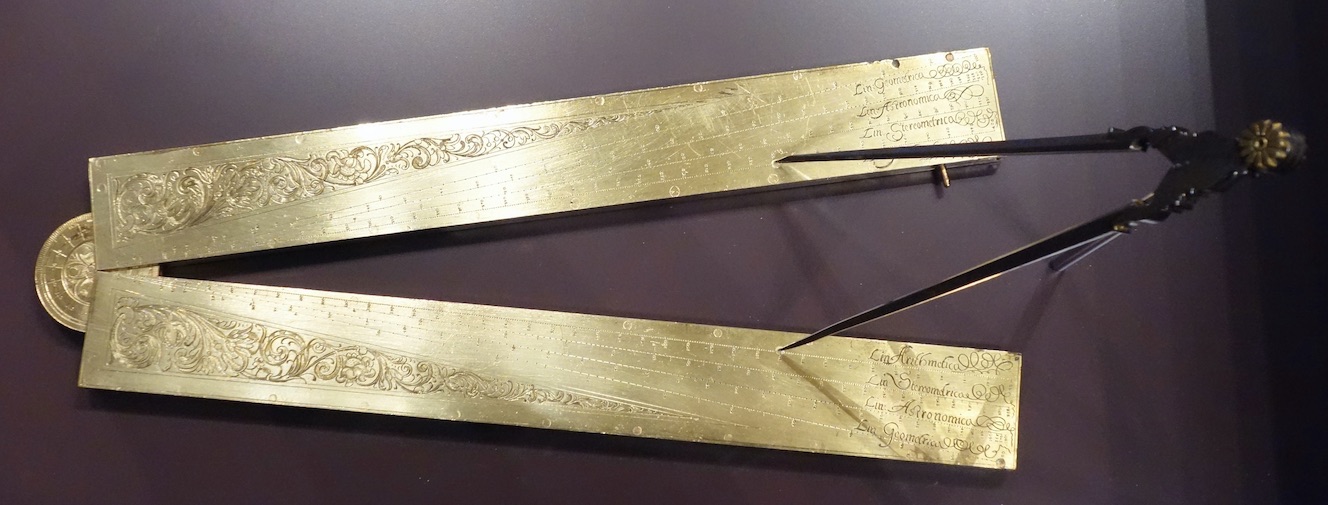
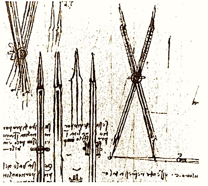
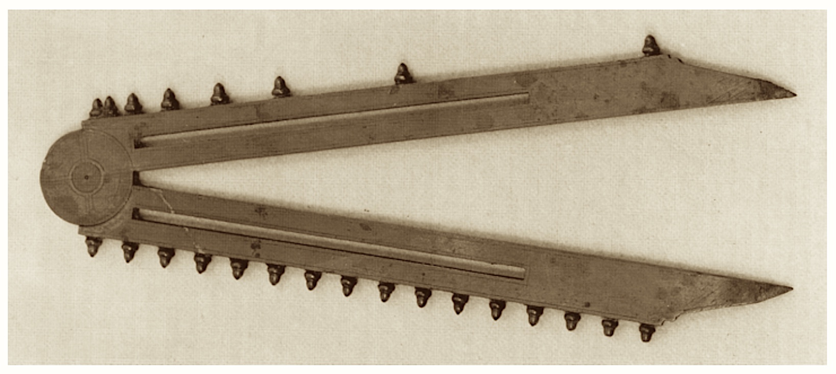
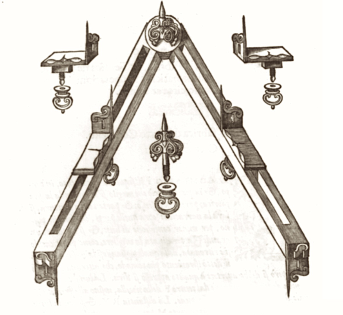
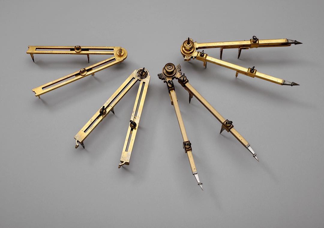
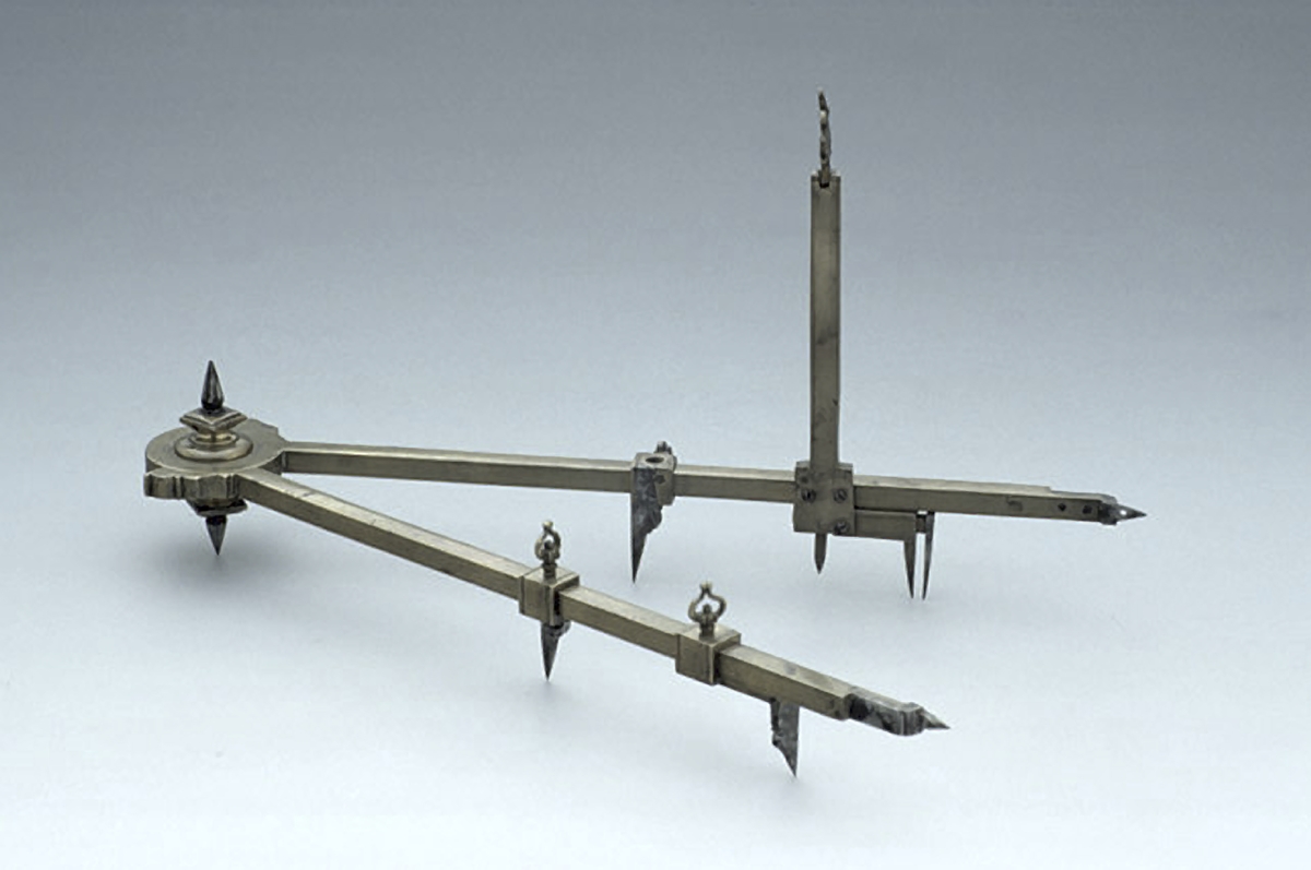
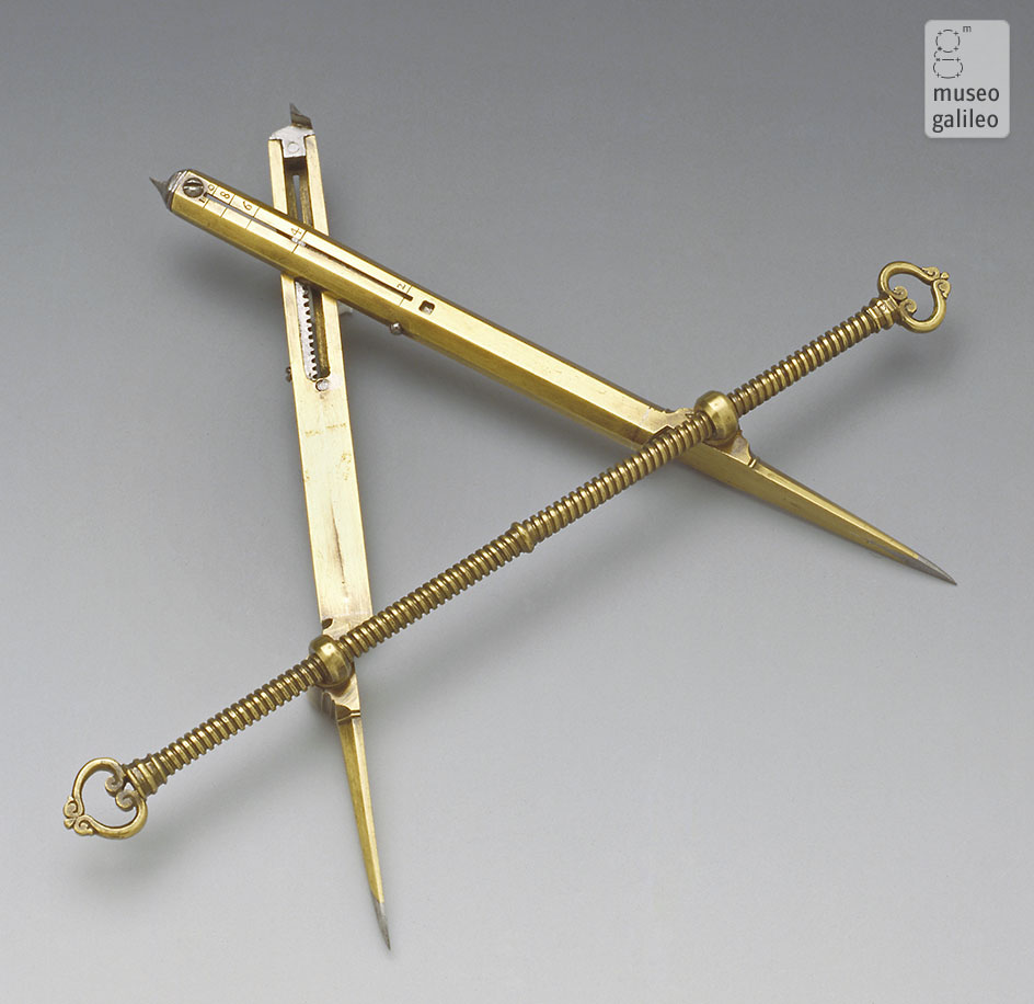
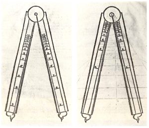
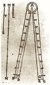
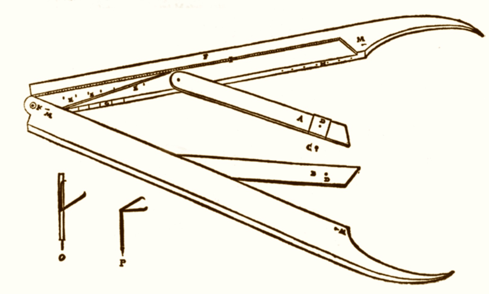
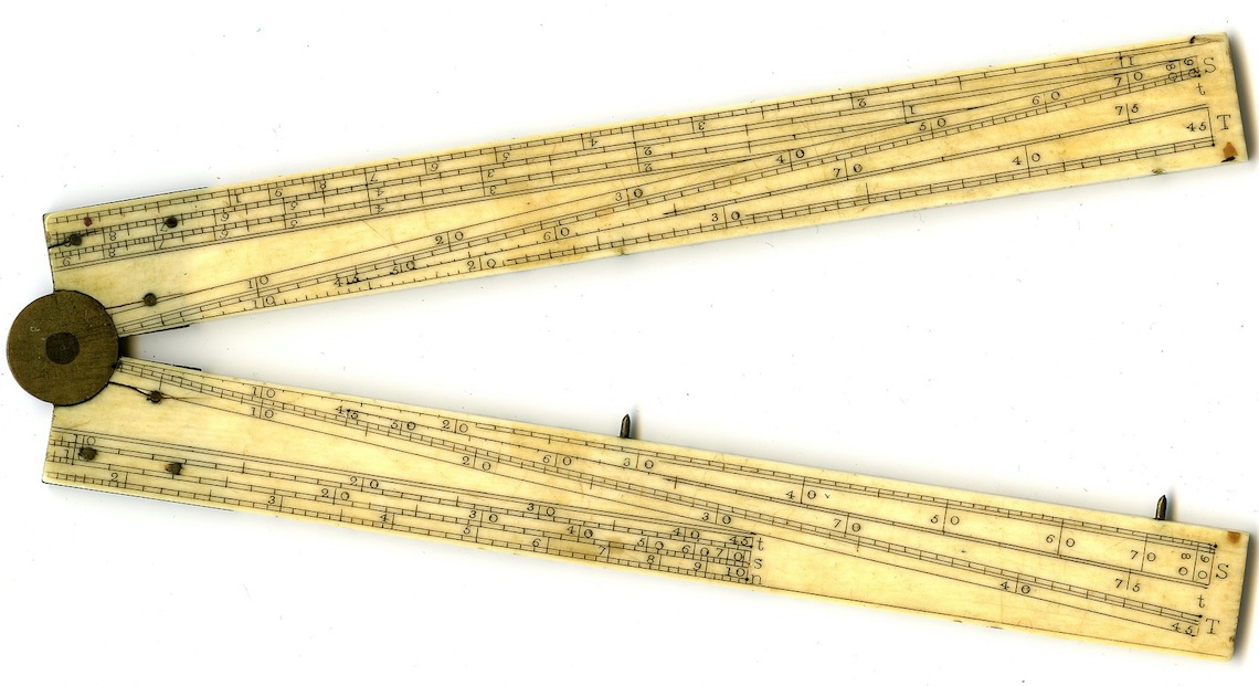
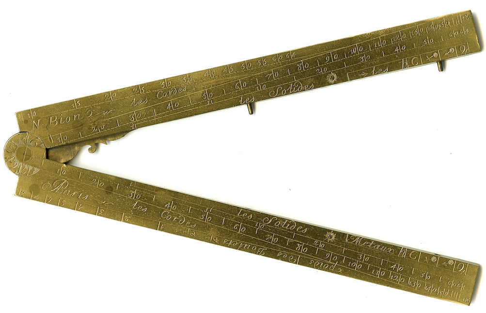
Fabrizio Mordente produced a first version of his compass in 1554. This was a four 4 point reduction compass with a ratio 1:60 between points, which served to measure accurately fractions of a degree. This was done to simplify the calculation of longitude by navigators. It was described  by Mordente in a brief note in 1567 in Venice (Modo di trovare con l’Astrolabio, o Quadrante, o altro instromento, oltre gradi, intieri, i minuti, et secondi, et ogn’altra particella). Between 1568 and 1570 Mordente  designed a new version of the instrument dedicated to the Duke Guidobaldo II della Rovere and named in his honor the roverino compass. The compass was made by Simone Barocci, who also made Commandino’s compass. Mordente’s compass was made with two flat legs with slits,  in which could move two sliders with tips positioned orthogonal to the legs. A third version was designed, which was described at length in a text written in 1584 by his brother Gasparo, himself the inventor of the parallel ruler (two rulers attached to each other enabling them to slide parallel to each other and which had proportional scales marked on both rules): Il compasso del s. Fabritio Mordente con altri istromenti mathematici ritrovati da Gasparo suo fratello. In the following years Mordente developed an eight point and then a nine point compass.

Mordente's second compass ca.1570. ©Venezia, Museo Correr, cl. XXIX, n° 78.
Mordente's third compass, 1584.
Fabrizio Mordente compasses. Courtesy of Adler Planetarium, Chicago illinois.
Mordente type multipoint compas. ( © Museum of the History of Science, Oxford. 
Inventory no. 49857

Federico Commandino developed a proportional compass apparently on request of the anatomist Bartolomeo Eustachi in 1568. In Eustachi’s approach reading  his Anatomical drawings  required the use of an instrument capable of easily dividing a line into equal parts. Thus a variable pivot proportional compass (as illustrated by da Vinci)  could satisfy this need and Commandino designed  one incorporating a micrometer screw for exact opening of the legs. This type of divider is still in use.

A modified version of this instrument was deveoped around 1570 by Guidobaldo del Monte. As described (1633) by engineer and mathematician, and student of Guidobaldo, Muzio Oddi, this new version was formed of two flat brass rulers hinged at one end. The flat legs were engraved with radial straight lines subdivided into segments: on one side, as in Commandino’s compass, for the different reduction ratios, on the other, according to the sides of  regular polygons inscribed in a circle having a diameter equal to the separation between the pointers on the legs of the compass (see Clavio’s version in the images below). The compass could be used to divide lines and circumferences into equal parts and for drawing regular polygons.

M.Oddi text on proportional compasses.
F. Commandino type proportional compass. ©Museo Galilei. Inv. 633
Guidobaldo type compass from G.P. Gallucci, "Della fabrica et uso di diversi strumenti...", Venezia, 1598, ch. 21. (2).
Guidobaldo type compass showing radial lines from C. Clavio, Geometria Practica, Roma, 1604, I, I (1)

Other 16th century Instruments.

A number of other proportional compasses were developed in the same period for military, astronomical and other uses. Amongst these are the compasses of the Italians Carlo Teti, Antonio Lupicini, Antonio Bianchini, Baldassare Lanci, Latino Orsini, the Englishman Humphrey Cole,  the Frenchman Jacques Besson, a few of which are illustrated here. Some of these, sometimes unusual designs, included determination of other useful quantities. Thus the compass of Teti, included the determination of  gauges of artilleries and the diameters of the cannon balls whose weight, in proportion to their diameter, was indicated  on the scale of weights (see e.g. F.Camerota and Museo Galilei for the details on these designs).  

Military compass of C.Teti
A.Bianchini's compass. ©Museo Galilei.
H.Cole compass. © Museo Galilei.
"Radio Latino": L.Orsini's compass. © Museo Galilei.

The Hood and Galileo Compasses/Sectors.

The end of the 16th century was marked by the appearance, of what are sometimes called (Drake 1976) calculating compasses, developed apparently independently by Thomas Hood in England (who termed his instrument: sector) and Galileo Galilei in Italy. They were calculating instruments in the sense that they carried scales allowing direct rapid evaluation of more complex quantities than possible with Mordente’s or Guidobaldo’s compasses: line divisions and polygon side deduction, and which would have required calculations beyond the grasp of the layman of the time.

In England, Thomas Hood published a detailed description of his sector in 1598: “The making and use of the Geometricall instrument called a Sector”. The instrument  was constructed by Charles Whitwell. His sector, originated possibly as a surveying instrument. Indeed its accessories included a pair of removable sights, a plumb line and a graduated quadrant attached to one arm, allowing to measure the angle of its opening. Besides the two arms carrying proportional scales, it had an additional arm, that could slide along the arm holding the quadrant. This arm allowed the direct calculation of strings, sines and cosines for any opening angle of the compass. 

Thomas Hood book
Thomas Hood's sector. From his description.
Galileo Galilei's proportional compass. Museo Galilei.
Galileo Galilei's compass instruction manual.

Galileo Galilei’s sector, designed around 1597, appears to have debuted with military uses in mind, as a combined and improved version of Tartaglia’s instruments (Drake), to which were progressively added scales for other uses. A number of  copies of this instrument were made by Galileo’s instrument maker: Marc’Antonio Mazzoleni. In 1606 Galileo published a detailed instruction manual describing 32 uses of his compasso: “Le operazioni del compasso geometrico et militare“. Sixty copies of the manual were published and were sold accompanied by the compass.

The Galilean sector is made up of :two legs, held together by a round disk (pivot), whose faces (front and back) are engraved with various scales;

  • the quadrant, graduated with four scales, which is fixed by means of wing nuts to the holes in the compass legs;
  • the clamp, a cursor inserted into one of the compass legs, which kept the instrument vertical and could serve as an extension for the leg to which it was attached.

The seven proportional lines drawn on the legs of the sector and the four scales marked on the dial, made it possible to easily perform all sorts of arithmetic and geometric operations. These varied from the calculation of interests to the extraction of square and cubic roots; from the design of the polygons to the calculation of areas and volumes. One of the uses was for gunnery.

The back of the legs show:

  • the arithmetic lines, on which are marked integers up to 250;

  • the geometric lines numbered from 1 to 50. Their primary function is that of indicating the sides of the squares whose areas are the indicated numbers. Thus the distance from the centre of the compass to each of the indicated numbers represents the square root of that number;
  • the stereometric lines, marked with numbers up to 140, and indicate the sides of the cubes whose volume is the indicated number. Thus the distance from the centre of the compass to each of the numbers indicated, equals the cube root of the numbers shown.
  • the metallic lines, which are marked with the names of eight materials: gold, lead, silver, copper, iron, tin, marble and stone. Given a constant weight W, each mark on the line indicates the diameter of a sphere of one of the eight materials whose weight is W. The marks closest to the centre of the compass, thus indicate the materials with a greater specific weight.

The front of the legs show:

  • the polygraphic lines, which gave the radii of circles circumscribing regular polygons having the same side. The polygons ranged from a triangle to a fifteen sided polygon. These lines are used to divide the circumference of a circle into a desired number of equal parts;
  • the tetragonic lines, indicate, given a certain surface S, the sides of the regular polygons that have that surface, from the triangle up to the polygon with thirteen sides;

  • the added lines have an internal and an external scale; the external scale, divided into twenty equal parts, is marked with the heights of the arced portion of twenty circular segments with the same chord; on the internal scale are marked twenty squares whose areas are equal to those of the respective circular segments. This is used to find the area of circular segments.

The quadrant had scales for four purposes: the bombardiers’ square; the astronomical quadrant; the scale of inclines, and the square of shadows.

A version of Galileo’s sector made by Giacomo Lusbergh is shown below.

G.Lusbergh compass description. 1698.
Galilean compasso version by Lusbergh

Galileo’s sector was widely circulated and copied, leading to severe authorship disputes, including one with his student Baldassarre Capra. In the following years various variants of the instrument were made in Europe and  presented under different names like the Flemish scientist Michel Coignet’s pantone compass, Ottavio Revesi Bruti’s archisesto, by Girard Desargues and others in France who called it optical or perspective compass. 

The English professor of Astronomy  Edmund Gunter (1581-1626), made a sector and wrote the book Description and Use of the Sector, first published in 1623. His sector included scales of logarithmic numbers, sines, and tangents. They also provided tools for trigonometry (tangent, sine, and secant) and for navigation (rhumbs and longitude). 

sector edmund gunter 1924
The sector of Edmund Gunter as given in his 1624 book.

Compass or Sector families.

Ultimately three styles of sectors, that differ by the sets of scales on the legs, evolved and are referred to as the Italian, English and French sectors. 

The English sectors evolved following the design by Gunter and by 1672 had additional logarithmic scales as may be seen in the image below. The French sectors, besides the Galilean lines, included lines for determination of the weight (poid des boulets) and calibre(size) of artillery shots (calibre des pieces).

The Construction and Principal Uses of Mathematical Instruments by Edmund Stone (1793).
The French sector and the English sector, in The Construction and Principal Uses of Mathematical Instruments of Bion, Nicolas translated by Edmund Stone (1723). Book 2, page 69.
19th Century English style sector. Inv. MA.321755. © The National Museum of American History.
French Style Sector by Nicholas Bion. 1681-1733. Inv. MA.321675. ©The National Museum of American History.

Miscellaneous Images.

Nova Scientia by Niccolo Tartaglia (1537)
The Description and Use of the Sector, by Edmund Gunter (1624).
P.Galluci "Della fabrica et uso di diversi strumenti di Astronomia et Cosmographia", Venice, 1598.
Denis Henrion & Jean Deshayes - L'usage du compas de proportion (1685)
Person using the Proportional Compass. From Henrion (1685)
A sector on a 50 Deutsche Mark “Balthasar Neumann” banknote. B.Neumann (1687-1753) was a German architect and instrument maker.

References.

  • Camerota Filippo. Il Compasso Geometrico E Militare Di Galileo Galilei, published by Istituto E Museo Di Storia Della Scienza, Florence (2004).
  • Drake Stillman 1976.  Galileo and the First Mechanical Computing Device. Scientific American 234, 104-13, http://www.jstor.org/stable/24950332.
  • Erwin Tomash Erwin and Williams Michael R., 2003.   The Sector: its history, scales, and uses. IEEE the Annals of the History of Computing, vol 25, pp 34-47, (2003); http://doi.ieeecomputersociety.org/10.1109/MAHC.2003.1179877
  • Frémontier-Murphy Camille,2013.  A New Mathematical Vision for an Innovative Calculating Instrument: Galileo’s Sector, Bulletin of the Scientific Instrument Society, n° 118 (2013), p. 35-43. (French version : http://culturemath.ens.fr/content/le-compas-de-proportion-de-galilée-et-les-mathématiques-des-ingénieurs-de-lépoque-moderne)
  • Galluci Paolo, 1598.  “Della fabrica et uso di diversi strumenti di Astronomia et Cosmographia”, Venice, 1598.
  • Gamba Enrico e Roberto Mantovani Roberto, 2013.  Gli strumenti scientifici di Guidobaldo del Monte. (Chapter 10, in: Antonio Becchi, Domenico Bertoloni Meli and Enrico Gamba (eds.): Guidobaldo del Monte (1545–1607) : Theory and Practice of the Mathematical Disciplines from Urbino to Europe; http://mprl-series.mpg.de/proceedings/4/).
  • Gunter Edmund. 1624. The Description and Use of the Sector, the Crosse-Staffe and other instruments.
  • Gunter Edmund, with Henry Bond and Samuel Foster.  1673. The works of that Famous Mathematician Edmund Gunter. Fifth edition carefully revised and somewhat augmented.
  • Henrion Denis and  & Deshayes Jean, 1685. L’usage du compas de proportion (1685)
  • Hénin Silvio, 2012. Early Italian Computing Machines and Their Inventors. In: Tatnall A. (eds) Reflections on the History of Computing. IFIP Advances in Information and Communication Technology, vol 387. (2012). Springer, Berlin, Heidelberg. doi.org/10.1007/978-3-642-33899-1_14.
  • Hood Thomas, 1598. The making and use of the Geometrical Instrument called a Sector. London
  • Pisano Raffaele and Bussotti Paolo, 2015.  Galileo in Padua: architecture, fortifications, mathematics and ‘‘practical’’ science, Lett. Mat. Int., 2, 209–222; DOI 10.1007/s40329-014-0068-.
  • Ruggieri Nicola, 2017.  Macchine, Strumenti, Utensìli e Attrezzi di Cantiere a Pompei nel I Secolo DC, Bollettino Ingegneri, 9- 10.
  • Stone Edmund, 1793. The Construction and Principal Uses of Mathematical Instruments by Edmund Stone.  from Nicolas Bion text  translation. https://archive.org/details/constructionprin00bion